POWER MIRROR CONTROL SYSTEM Mirror Heater does not Operate with Rear Defogger Switch
DESCRIPTION
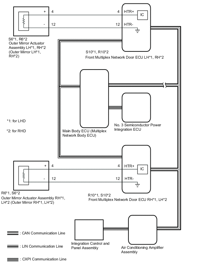
When the mirror heater switch (rear window defogger switch) is operated, the mirror heater signal is sent to the air conditioning amplifier assembly and then to each front multiplex network door ECU via CAN communication. Based on this signal, the front multiplex network door ECUs operate the mirror heaters.
WIRING DIAGRAM
CAUTION / NOTICE / HINT
Note
-
The power mirror control system uses the CAN communication system, CXPI communication system and power integration system. First, confirm that there is no malfunction in the above systems. Refer to the How to Proceed with Troubleshooting procedure.
-
If the battery voltage is low, the mirror heater function may not operate. When "Operation of Electrical Items Restricted." is not displayed on the multi-information display in the combination meter assembly, check the Data List item "Battery Control Count (Body ECU)".
-
Before replacing the main body ECU (multiplex network body ECU), refer to Service Bulletin.
PROCEDURE
-
CHECK WINDOW DEFOGGER SYSTEM
-
Check window defogger system operation.
OK Window defogger system is normal. Result Proceed to OK NG
NG 
GO TO WINDOW DEFOGGER SYSTEM Click here
OK 
-
-
PERFORM ACTIVE TEST USING GTS (MIRROR HEATER)
-
Connect the GTS to the DLC3.
-
Turn the engine switch on (IG).
-
Turn the GTS on.
-
Enter the following menus: Body Electrical / Front Left Door or Front Right Door / Active Test.
-
Perform an Active Test according to the display on the GTS.
Body Electrical > Front Left Door > Active TestTester Display Measurement Item Control Range Diagnostic Note Mirror Heater Mirror heater operation OFF or ON
-
Operate with the engine switch on (IG) and the vehicle stopped.
-
This test turns the mirror heater on or off.
-
Mirror heater operation can be confirmed by touch.
Body Electrical > Front Left Door > Active TestTester Display Mirror Heater
Body Electrical > Front Right Door > Active TestTester Display Measurement Item Control Range Diagnostic Note Mirror Heater Mirror heater operation OFF or ON
-
Operate with the engine switch on (IG) and the vehicle stopped.
-
This test turns the mirror heater on or off.
-
Mirror heater operation can be confirmed by touch.
Body Electrical > Front Right Door > Active TestTester Display Mirror Heater Result Result Proceed to Mirror heater operation on both mirrors is normal A Mirror heater operation on driver door mirror is not normal B Mirror heater operation on front passenger door mirror is not normal C -
A
REPLACE AIR CONDITIONING AMPLIFIER ASSEMBLY Click here
C 
CHECK HARNESS AND CONNECTOR (OUTER MIRROR ACTUATOR ASSEMBLY (FRONT PASSENGER DOOR) - OUTER MIRROR CONTROL ECU ASSEMBLY (FRONT PASSENGER DOOR)) Click here
B
-
-
CHECK HARNESS AND CONNECTOR (OUTER MIRROR ACTUATOR ASSEMBLY (DRIVER DOOR) - FRONT ULTIPLEX NETWORK DOOR ECU (DRIVER DOOR))
-
for LHD:
-
Disconnect the S6 outer mirror actuator assembly LH connector.
-
Disconnect the S10 front multiplex network door ECU LH connector.
-
Measure the resistance according to the value(s) in the table below.
Standard Resistance Tester Connection Condition Specified Condition S6-4 (+) - S10-4 (HTR+) Always Below 1 Ω S6-4 (+) or S10-4 (HTR+) - Body ground Always 10 kΩ or higher S6-12 (-) - S10-12 (HTR-) Always Below 1 Ω S6-12 (-) or S10-12 (HTR-) - Body ground Always 10 kΩ or higher
-
-
for RHD:
-
Disconnect the R6 outer mirror actuator assembly RH connector.
-
Disconnect the R10 front multiplex network door ECU RH connector.
-
Measure the resistance according to the value(s) in the table below.
Standard Resistance Tester Connection Condition Specified Condition R6-4 (+) - R10-4 (HTR+) Always Below 1 Ω R6-4 (+) or R10-4 (HTR+) - Body ground Always 10 kΩ or higher R6-12 (-) - R10-12 (HTR-) Always Below 1 Ω R6-12 (-) or R10-12 (HTR-) - Body ground Always 10 kΩ or higher
Result Proceed to OK NG -
NG
REPAIR OR REPLACE HARNESS OR CONNECTOR
OK
-
-
INSPECT OUTER MIRROR ACTUATOR ASSEMBLY (DRIVER DOOR)
-
Remove the outer mirror actuator assembly (driver door).
-
Inspect the outer mirror actuator assembly (driver door).
Result Proceed to OK NG
OK
REPLACE FRONT MULTIPLEX NETWORK DOOR ECU (DRIVER DOOR) Click here
NG
-
-
INSPECT OUTER MIRROR (DRIVER DOOR)
-
Remove the outer mirror (driver door).
-
Inspect the outer mirror (driver door).
Result Proceed to OK NG
OK
REPLACE OUTER MIRROR ACTUATOR ASSEMBLY (DRIVER DOOR) Click here
NG
REPLACE OUTER MIRROR (DRIVER DOOR) Click here
-
-
CHECK HARNESS AND CONNECTOR (OUTER MIRROR ACTUATOR ASSEMBLY (FRONT PASSENGER DOOR) - OUTER MIRROR CONTROL ECU ASSEMBLY (FRONT PASSENGER DOOR))
-
for LHD:
-
Disconnect the R6 outer mirror actuator assembly RH connector.
-
Disconnect the R10 front multiplex network door ECU RH connector.
-
Measure the resistance according to the value(s) in the table below.
Standard Resistance Tester Connection Condition Specified Condition R6-4 (+) - R10-4 (HTR+) Always Below 1 Ω R6-4 (+) or R10-4 (HTR+) - Body ground Always 10 kΩ or higher R6-12 (-) - R10-12 (HTR-) Always Below 1 Ω R6-12 (-) or R10-12 (HTR-) - Body ground Always 10 kΩ or higher
-
-
for RHD:
-
Disconnect the S6 outer mirror actuator assembly LH connector.
-
Disconnect the S10 front multiplex network door ECU LH connector.
-
Measure the resistance according to the value(s) in the table below.
Standard Resistance Tester Connection Condition Specified Condition S6-4 (+) - S10-4 (HTR+) Always Below 1 Ω S6-4 (+) or S10-4 (HTR+) - Body ground Always 10 kΩ or higher S6-12 (-) - S10-12 (HTR-) Always Below 1 Ω S6-12 (-) or S10-12 (HTR-) - Body ground Always 10 kΩ or higher
Result Proceed to OK NG -
NG
REPAIR OR REPLACE HARNESS OR CONNECTOR
OK
-
-
INSPECT OUTER MIRROR ACTUATOR ASSEMBLY (FRONT PASSENGER DOOR)
-
Remove the outer mirror actuator assembly (front passenger door).
-
Inspect the outer mirror actuator assembly (front passenger door).
Result Proceed to OK NG
OK
REPLACE MULTIPLEX NETWORK DOOR ECU (FRONT PASSENGER DOOR) Click here
NG
-
-
INSPECT OUTER MIRROR (FRONT PASSENGER DOOR)
-
Remove the outer mirror (front passenger door).
-
Inspect the outer mirror (front passenger door).
Result Proceed to OK NG
OK
REPLACE OUTER MIRROR ACTUATOR ASSEMBLY (FRONT PASSENGER DOOR) Click here
NG
REPLACE OUTER MIRROR (FRONT PASSENGER DOOR) Click here
-