FRONT DOOR REASSEMBLY

CAUTION / NOTICE / HINT
Tech Tips
-
Use the same procedure as for the LHD and RHD vehicles.
-
The procedure listed below is for the LHD vehicles.
-
Use the same procedure for the RH side and LH side.
-
The procedure described below is for the LH side.
-
A bolt without a torque specification is shown in the standard bolt chart.
PROCEDURE
-
INSTALL STEP PANEL WIRE LH
-
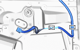
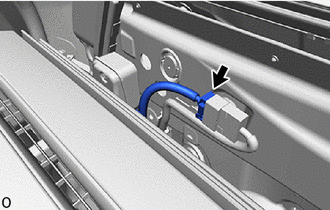
Attach the clamp to install the step panel wire LH.
-
-
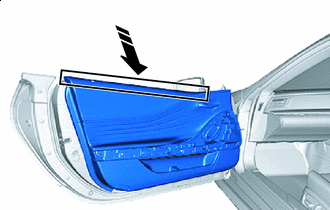
INSTALL FRONT DOOR NO. 2 WEATHERSTRIP LH
-
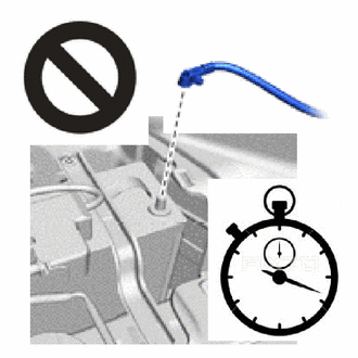
Remove the peeling paper from the face of a new front door No. 2 weatherstrip LH.
Tech Tips
After removing the peeling paper, keep the exposed adhesive free from foreign matter.
-
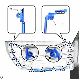
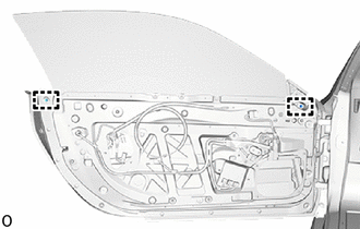
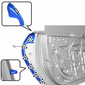
*1 Grommet 
Double-sided Tape Attach the grommet and double-sided tape.
-
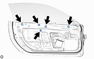
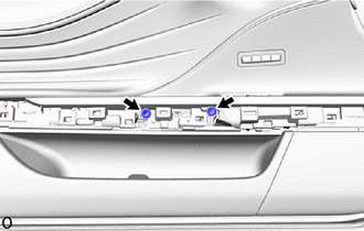
Attach the clips to install the front door No. 2 weatherstrip LH.
Tech Tips
Press the front door No. 2 weatherstrip LH firmly to install it.
-
-
INSTALL FRONT DOOR BELT MOULDING ASSEMBLY LH
-
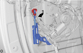
INSTALL FRONT DOOR LOCK CYLINDER ASSEMBLY LH
-
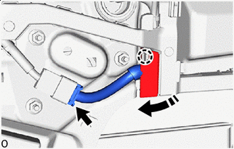
Put the outside door handle in the full stroke position and install the front door lock cylinder assembly LH.
-
Using a T30 "TORX" socket wrench, install the front door lock cylinder assembly LH with the "TORX" screw.
- Torque:
- 4.0 N*m { 41 kgf*cm, 35 in.*lbf }
-
-
INSTALL OUTSIDE DOOR HANDLE SUB-ASSEMBLY LH
-
Apply MP grease to the sliding area of the outside door handle sub-assembly LH.
-
Temporarily install the outside door handle sub-assembly LH with the 4 bolts.
-
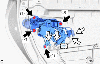

Bolt 
Connector Tighten the 4 bolts in the order shown in the illustration to install the outside door handle sub-assembly LH.
- Torque:
- 5.5 N*m { 56 kgf*cm, 49 in.*lbf }
Note
When tightening the handle, check there is no significant gaps or differences.
-
Connect the 4 connectors and attach the clamp.
-
Remove the protective tape.
-
-
INSTALL FRONT DOOR PANEL CUSHION
-
Attach the claws to install a new front door panel cushion.
-
-
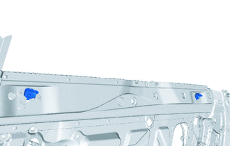
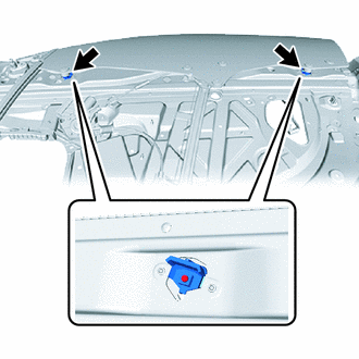
INSTALL HOLE PLUG
-
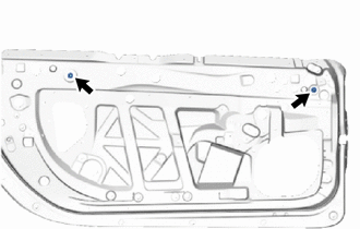
for Front Door Inside Panel Side:
Install the 2 hole plugs.
-
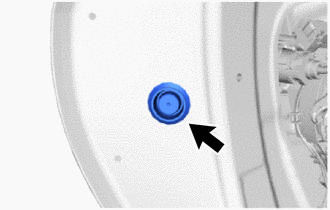
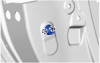
for Front Door Outer Panel Side:
Install the hole plug.
-
-
INSTALL FRONT DOOR WIRE LH
-
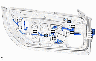
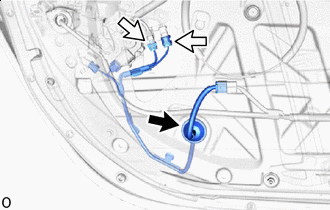
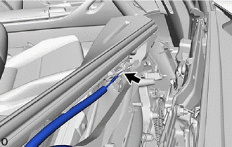
Attach the clamps to install the front door wire LH.
-
-
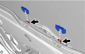
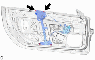
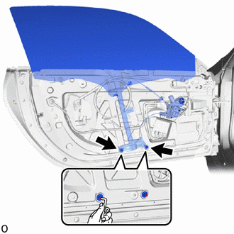
INSTALL FRONT DOOR WINDOW REGULATOR SUB-ASSEMBLY LH
-
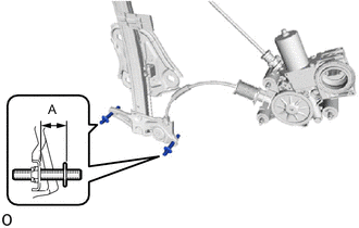
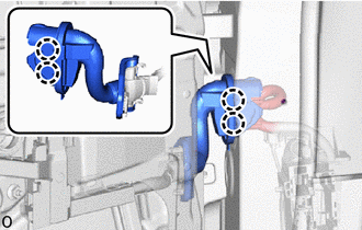
Using a 4.0 mm hexagon wrench, adjust the 2 stud bolts at the bottom of the front door window regulator assembly LH as shown in the illustration.
Standard Clearance Area Specified Condition A 20.9 to 21.9 mm (0.823 to 0.862 in.) -
Apply MP grease to the sliding and rotating areas of the front door window regulator sub-assembly LH.
-
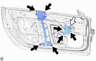
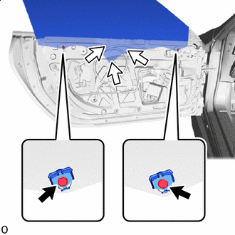
Nut Connector Temporarily install the front door window regulator assembly LH with the 7 nuts.
-
Connect the connector.
-
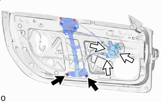
Nut <A> Nut <B> Tighten the 2 nuts <A> and 3 nuts <B>.
- Torque:
- Nut <A>
- 13 N*m { 133 kgf*cm, 10 ft.*lbf }
- Nut <B>
- 5.5 N*m { 56 kgf*cm, 49 in.*lbf }
-
-
INSTALL FRONT DOOR GLASS RUN LH
-
Install the front door glass run LH for the front door front lower frame sub-assembly LH.
Note
Make sure the hole on the end of the front door glass run LH is fitted securely to the protrusion on the lower part of the front door front lower frame sub-assembly LH.
-
-
INSTALL FRONT DOOR FRONT LOWER FRAME SUB-ASSEMBLY LH
-
Install the front door front lower frame sub-assembly LH with the 2 nuts.
- Torque:
- 7.5 N*m { 76 kgf*cm, 66 in.*lbf }
-
-
INSTALL FRONT DOOR UPPER WINDOW STOP
-
Temporarily install the 2 front door upper window stops.
-
-
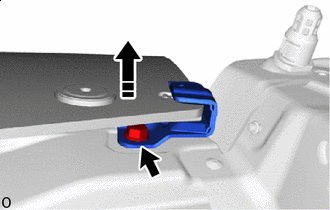
INSTALL FRONT DOOR GLASS SUB-ASSEMBLY LH
-
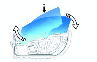

Install in this Direction (1) 
Install in this Direction (2) Slide the front door glass sub-assembly LH in the direction of the arrows shown in the illustration and install it to the carrier plate of the front door window regulator sub-assembly LH.
-
Install the front door glass sub-assembly LH with the 3 nuts.
- Torque:
- 8.0 N*m { 82 kgf*cm, 71 in.*lbf }
-
Tighten the 2 bolts to install the 2 front door upper window stops.
- Torque:
- 11.5 N*m { 117 kgf*cm, 8 ft.*lbf }
Note
Be careful not to damage the front door glass sub-assembly LH.
-
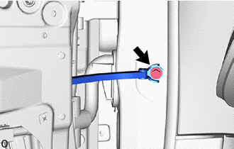
Move in this Direction Bolt Lift up the front door glass sub-assembly LH and install the door window female stabilizer LH with the bolt.
- Torque:
- 5.5 N*m { 56 kgf*cm, 49 in.*lbf }
-
Install the 2 window regulator shims.
-
Tighten the 2 nuts to install the front door window regulator sub-assembly LH.
- Torque:
- 5.5 N*m { 56 kgf*cm, 49 in.*lbf }
-
Install the 5 hole plugs.
-
-
INSTALL FRONT DOOR CHECK ASSEMBLY LH
-
Apply MP grease to the sliding areas of the front door check assembly LH.
-
Install the front door check assembly LH with the 2 nuts.
- Torque:
- 8.0 N*m { 82 kgf*cm, 71 in.*lbf }
-
-
INSTALL FRONT DOOR LOCK WITH MOTOR ASSEMBLY LH
-
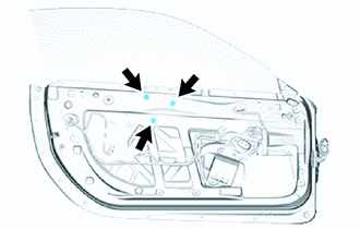
INSTALL FRONT DOOR INSIDE PANEL SUB-ASSEMBLY LH
Note
-
Although CFRP material has high strength, there is a possibility of cracking if an excessive load is applied. As a result, pay attention to how it is handled.
-
Perform this operation with 2 or more people because of the risk of deformation or damage.
-
Be careful not to damage the front door glass sub-assembly LH.
-
There are limited gaps between the end of the bolts and the door outer panel and readjusting the threading by tapping is difficult. As a result, the front door inside panel sub-assembly LH installation bolts and "TORX" screw ((7) and (8) in the illustration) should only be temporarily installed as not to damage the threads.
-
Set the front door inside panel sub-assembly LH center door guide piece on the front door panel sub-assembly LH.
-
Temporarily install the "TORX" bolt, 7 "TORX" screws and 3 front door inside plates.
-
Temporarily install the 4 bolts.
-
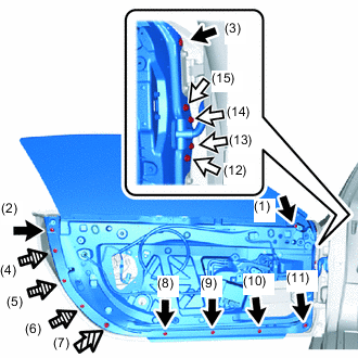
"TORX" screw Bolt 
"TORX" bolt
(w/ Rubber Cushion)

Front Door Inside Panel Plate
("TORX" screw)
Tighten the bolt, "TORX" bolt, "TORX" screw and front door inside plate in the order shown in the illustration.
-
"TORX" screw:
Using a T30 "TORX" socket wrench, tighten the 7 "TORX" screws.
- Torque:
- 11 N*m { 112 kgf*cm, 8 ft.*lbf }
-
Bolt:
Tighten the 4 bolts.
- Torque:
- 8.0 N*m { 82 kgf*cm, 71 in.*lbf }
-
"TORX" bolts (w/ Rubber Cushion)
Using a T30 "TORX" socket wrench, tighten the "TORX" bolts.
- Torque:
- 8.0 N*m { 82 kgf*cm, 71 in.*lbf }
-
Front door inside panel plate:
Using a T30 "TORX" socket wrench, tighten the 3 front door inside panel plates.
- Torque:
- 11 N*m { 112 kgf*cm, 8 ft.*lbf }
-
-
Attach the clamps.
-
Close in this Direction Connect the connector.
-
Close the wiring protector and attach the claw.
-
Grommet Connector Connect the 2 connectors and install the grommet.
-
Connect the front door wire harness connector and attach the claws.
-
Clean the bolt hole on the vehicle body.
-
Apply adhesive to the threads of the bolt.
Adhesive Toyota Genuine Adhesive 1324, Three Bond 1324 or equivalent. -
Install the bolt.
- Torque:
- 27 N*m { 275 kgf*cm, 20 ft.*lbf }
-
Install in this Direction Insert your hand into the service hole, attach the door lock side rod and install the snap lock.
-
-
INSPECT FRONT DOOR GLASS SUB-ASSEMBLY LH
-
Check that the clearance measurements of areas a through m are within each standard range.
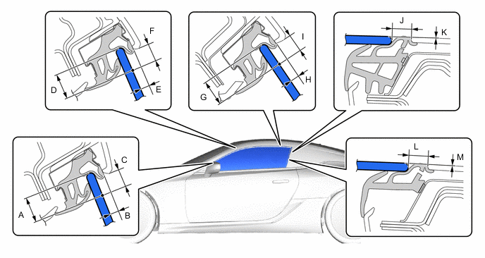
Standard Clearance Area Measurement Area Measurement A
(Reference)
15.0 mm (0.591 in.) B 3.1 to 7.1 mm (0.122 to 0.280 in.) C 8.7 to 12.7 mm (0.343 to 0.500 in.) D
(Reference)
15.0 mm (0.591 in.) E 3.2 to 7.2 mm (0.126 to 0.283 in.) F 8.5 to 12.5 mm (0.335 to 0.492 in.) G
(Reference)
15.0 mm (0.591 in.) H 3.2 to 7.2 mm (0.126 to 0.283 in.) I 7.6 to 11.6 mm (0.299 to 0.457 in.) J 10.0 to 14.0 mm (0.394 to 0.551 in.) K
(Reference)
0 mm (0 in.) L 10.0 to 14.0 mm (0.394 to 0.551 in.) M
(Reference)
0 mm (0 in.) - -
-
-
ADJUST FRONT DOOR GLASS SUB-ASSEMBLY LH
-
Adjust the fit of the top part of the front door glass sub-assembly LH inward and outward.
-
Loosen the 2 nuts at the bottom of the front door window regulator assembly LH.
-
Using a 4.0 mm hexagon wrench, turn the 2 stud bolts to adjust the fit of the top part of the front door glass sub-assembly LH inward and outward.
Tech Tips
When the stud bolt are turned counterclockwise, the top part of the front door glass sub-assembly LH moves toward the inside of the vehicle. When the stud bolt are turned clockwise, the top part of the front door glass sub-assembly LH moves toward the outside of the vehicle.
-
Tighten the 2 nuts after adjustment.
- Torque:
- 13 N*m { 133 kgf*cm, 10 ft.*lbf }
-
-
Adjust the fit of the bottom part of the front door glass sub-assembly LH inward and outward.
-
Loosen the 2 nuts at the top of the front door window regulator assembly LH.
-
Change the number of installed window regulator shims to adjust the fit of the bottom part of the front door glass sub-assembly LH inward and outward.
Tech Tips
-
When more shims are used, the bottom part of the front door glass sub-assembly LH moves toward the outside of the vehicle. When less shims are used, the bottom part of the front door glass sub-assembly LH moves toward the inside of the vehicle.
-
The thickness of one window regulator shim is 1.0 mm (0.039 in.).
-
-
Tighten the 2 nuts after adjustment.
- Torque:
- 5.5 N*m { 56 kgf*cm, 49 in.*lbf }
-
-
Connect the cable to the negative (-) battery terminal.
-
for Driver Side:
Connect the No. 2 front door wire LH, multiplex network master switch assembly and front door multiplex network ECU LH connectors.
-
for Front Passenger Side:
Connect the No. 2 front door wire RH, power window regulator switch assembly and front door multiplex network ECU RH connectors.
-
Front Upper Door Window Stop Nut Adjust the front door glass sub-assembly LH fully closed position horizontally and vertically.
-
Loosen the 2 front door upper window stop bolts and temporarily move the front door upper window stops to the top of their adjustment range and then temporarily install the bolts.
-
Loosen the 3 front door glass sub-assembly LH nuts.
-
Stop the front door glass sub-assembly LH approximately 3 mm (0.118 in.) below the fully closed position.
-
While holding the front door glass sub-assembly LH, move it vertically and horizontally to adjust its position.
-
Tighten the 3 nuts after adjustment.
- Torque:
- 8.0 N*m { 82 kgf*cm, 71 in.*lbf }
-
Move the front door glass sub-assembly LH to the fully closed position.
-
Loosen the 2 front door upper window stop bolts.
-
While lightly pushing each front door upper window stop against the stopper on the front door glass sub-assembly, tighten each bolt.
- Torque:
- 11.5 N*m { 117 kgf*cm, 8 ft.*lbf }
-
-
Disconnect the cable from the negative (-) battery terminal.
CAUTION:
Wait at least 90 seconds after disconnecting the cable from the negative (-) battery terminal to disable the SRS system.
Note
When disconnecting the cable, some systems need to be initialized after the cable is reconnected.
-
for Driver Side:
Disconnect the No. 2 front door wire LH, multiplex network master switch assembly and multiplex network front door ECU LH connector.
-
for Front Passenger Side:
Disconnect the No. 2 front door wire RH, power window regulator switch assembly and multiplex network front door ECU RH connector.
-
-
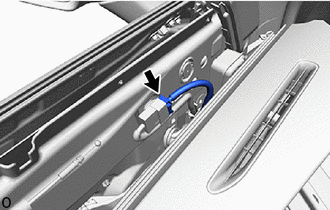
INSTALL REAR ACCESS PANEL WEATHERSTRIP LH
-
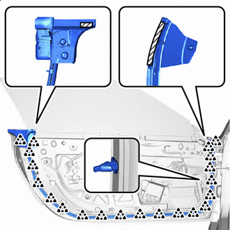
Remove the peeling paper from the face of a new rear access panel weatherstrip LH.
-
*a Clip <A> Double-sided Tape Attach the double-sided tape.
-
Install the clip <A>.
-
Attach the clips to install the rear access panel weatherstrip LH.
Tech Tips
Press the rear access panel weatherstrip LH firmly to install it.
-
-
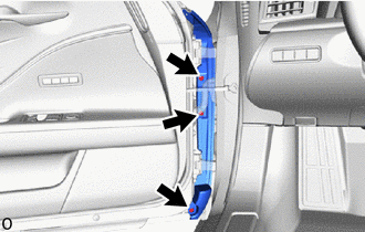
INSTALL FRONT DOOR TRIM SEAL LH
-
Attach the clips to install the front door trim seal LH.
-
-
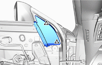
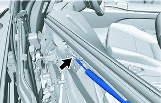
INSTALL FRONT DOOR WEATHERSTRIP LH
-
Remove the peeling paper from the face of a new front door weatherstrip LH.
-
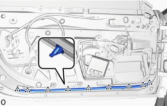
Double-sided Tape Attach the double-sided tape.
-
Attach the clips to install the front door weatherstrip LH.
Tech Tips
Press the front door weatherstrip LH firmly to install it.
-
-
INSTALL FRONT DOOR NO. 3 WEATHERSTRIP LH
-
Install the front door No. 3 weatherstrip LH with the 3 clips.
-
-
INSTALL FRONT DOOR DIVISION BAR SEAL LH
-
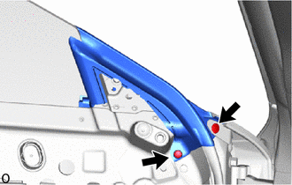
Install the front door division bar seal LH with the 2 clips.
-
-
INSTALL FRONT DOOR FRONT LOWER FRAME UPPER COVER LH
-
INSTALL DOOR SIDE AIRBAG SENSOR LH
-
INSTALL NO. 1 FRONT DOOR HOLE COVER SUB-ASSEMBLY LH
-
INSTALL FRONT DOOR MULTIPLEX NETWORK ECU LH
-
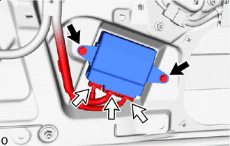
Screw Connector Install the front door multiplex network ECU LH with the 2 screws.
-
Connect the 3 connectors.
-
-
INSTALL NO. 1 SPEAKER ASSEMBLY WITH BOX
-
INSTALL FRONT DOOR LOWER FRAME BRACKET GARNISH LH
-
Attach the clips to install the front door lower frame bracket garnish LH.
-
-
INSTALL OUTER REAR VIEW MIRROR ASSEMBLY LH
-
INSTALL NO. 2 FRONT DOOR WIRE LH
-
Connect the connector, attach all of the each clamps to install the No. 2 front door wire LH.
-
-
INSTALL SEAT MEMORY SWITCH (for Driver Side)
-
INSTALL INDICATOR LIGHT COVER
-
INSTALL INDICATOR LIGHT BRACKET
-
INSTALL INDICATOR LIGHT ASSEMBLY
-
INSTALL FRONT DOOR INNER GLASS WEATHERSTRIP LH
-
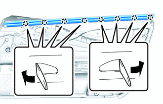
Bend the claws as shown in the illustration and install the front door inner glass weatherstrip LH to the front door trim board sub-assembly LH.
-
-
INSTALL FRONT DOOR INSIDE HANDLE SUB-ASSEMBLY LH
-
Install the front door inside handle sub-assembly LH with the 4 screws.
-
-
INSTALL MULTIPLEX NETWORK MASTER SWITCH ASSEMBLY (for Driver Side)
-
INSTALL FRONT DOOR TRIM BOARD SUB-ASSEMBLY LH (for Driver Side)
-
Connect the connector.
-
Connect the front door lock remote control cable assembly LH for the front door inside handle sub-assembly LH.
-
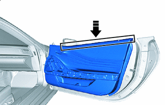
Install in this Direction Insert the front door trim board sub-assembly LH into the front door panel to set the front door panel sub-assembly LH.
-
Attach the clips to install the front door trim board sub-assembly LH.
-
Install the 2 screws.
-
-
INSTALL COURTESY LIGHT ASSEMBLY LH (for Driver Side)
-
INSTALL FRONT DOOR TRIM COVER SUB-ASSEMBLY LH (for Driver Side)
-
Attach the clips to install the front door trim cover sub-assembly LH.
-
-
INSTALL POWER WINDOW REGULATOR SWITCH ASSEMBLY (for Front Passenger Side)
-
INSTALL FRONT DOOR TRIM BOARD SUB-ASSEMBLY RH (for Front Passenger Side)
-
Connect the connector.
-
Connect the front door lock remote control cable assembly RH for the front door inside handle sub-assembly RH.
-
Install in this Direction Insert the front door trim board sub-assembly RH into the front door panel to set the front door panel sub-assembly RH.
-
Attach the clips to install the front door trim board sub-assembly RH.
-
Install the 3 screws.
-
-
INSTALL COURTESY LIGHT ASSEMBLY RH (for Front Passenger Side)
-
INSTALL FRONT DOOR ASSIST GRIP ASSEMBLY RH (for Front Passenger Side)
-
Attach the clips to install the front door assist grip assembly RH.
-
-
CONNECT CABLE TO NEGATIVE BATTERY TERMINAL
Note
When disconnecting the cable, some systems need to be initialized after the cable is reconnected.
-
INSTALL NO. 2 DECK BOARD
-
INITIALIZE POWER WINDOW CONTROL SYSTEM
-
POWER WINDOW OPERATION
-
INSPECT SRS WARNING LIGHT
-
INSPECT DOOR LOCK OPERATION