FLUSH HANDLE SYSTEM Only the Front Passenger Side Flush Handle Extension or Retraction Operation does not Repeatedly Operate
DESCRIPTION
The signals of each switch from inside the door outside handle sub-assembly RH*1 or door outside handle sub-assembly*2 in the driver side flush handle are sent to the main body ECU (multiplex network body ECU) through the front multiplex network door ECU RH*1 or front multiplex network door ECU LH*2. The main body ECU (multiplex network body ECU) performs operation judgment based on input signals and sends operation request signals to the front multiplex network door ECU RH*1 or front multiplex network door ECU LH*2.
-
*1: for LHD
-
*2: for RHD
WIRING DIAGRAM
-
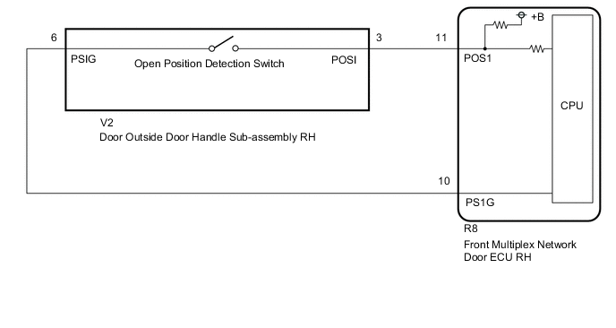
for LHD
-
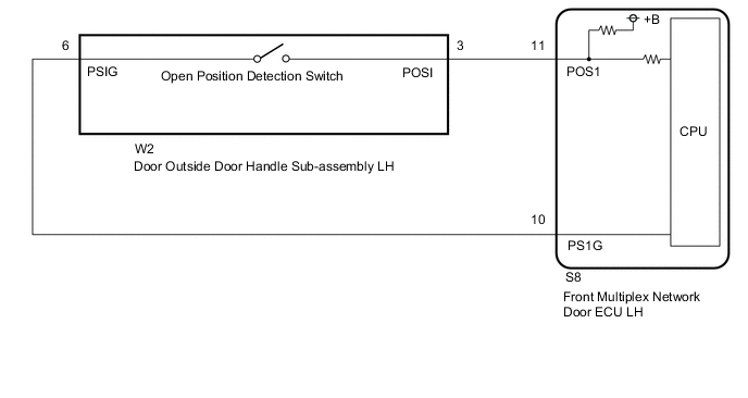
for RHD
PROCEDURE
-
CHECK VEHICLE TYPE
-
Check the vehicle type.
Result Result Proceed to for LHD A for RHD B
B 
READ VALUE USING GTS Click here
A 
-
-
READ VALUE USING GTS
-
Read the Data List according to the display on the GTS.
Body Electrical > Front Right Door > Data ListTester Display Measurement Item Range Normal Condition Diagnostic Note Flash Handle Position Switch Displays the position of the door outside handle sub-assembly RH Fold or Return Fold: Door outside handle sub-assembly RH retracted (open position detection switch off)
Return: Door outside handle sub-assembly RH opened (open position detection switch on)
-
Body Electrical > Front Right Door > Data ListTester Display Flash Handle Position Switch OK The Data List changes according to the door outside handle sub-assembly RH operation. OK Proceed to OK NG
OK 
REPLACE FRONT MULTIPLEX NETWORK DOOR ECU RH Click here
NG
-
-
INSPECT DOOR OUTSIDE HANDLE SUB-ASSEMBLY RH (OPEN POSITION DETECTION SWITCH)
-
Remove the door outside handle sub-assembly RH (open position detection switch).
-
Inspect the door outside handle sub-assembly RH (open position detection switch).
OK Proceed to OK NG
NG
REPLACE DOOR OUTSIDE HANDLE SUB-ASSEMBLY RH (OPEN POSITION DETECTION SWITCH) Click here
OK
-
-
CHECK HARNESS AND CONNECTOR (FRONT MULTIPLEX NETWORK DOOR ECU RH - DOOR OUTSIDE HANDLE SUB-ASSEMBLY RH)
-
Disconnect the R8 front multiplex network door ECU RH connector.
-
Disconnect the V2 door outside handle sub-assembly RH connector.
-
Measure the resistance according to the value(s) in the table below.
Standard Resistance Tester Connection Condition Specified Condition R8-10 (PS1G) - V2-6 (PSIG) Always Below 1 Ω R8-11 (POS1) - V2-3 (POSI) Always Below 1 Ω R8-10 (PS1G) or V2-6 (PSIG) - Body ground Always 10 kΩ or higher R8-11 (POS1) or V2-3 (POSI) - Body ground Always 10 kΩ or higher Result Proceed to OK NG
OK
REPLACE FRONT MULTIPLEX NETWORK DOOR ECU RH Click here
NG
REPAIR OR REPLACE HARNESS OR CONNECTOR
-
-
READ VALUE USING GTS
-
Read the Data List according to the display on the GTS.
Body Electrical > Front Left Door > Data ListTester Display Measurement Item Range Normal Condition Diagnostic Note Flash Handle Position Switch Displays the position of the door outside handle sub-assembly LH Fold or Return Fold: Door outside handle sub-assembly LH retracted (open position detection switch off)
Return: Door outside handle sub-assembly LH opened (open position detection switch on)
-
Body Electrical > Front Left Door > Data ListTester Display Flash Handle Position Switch OK The Data List changes according to the door outside handle sub-assembly LH operation. OK Proceed to OK NG
OK
REPLACE FRONT MULTIPLEX NETWORK DOOR ECU LH Click here
NG
-
-
INSPECT DOOR OUTSIDE HANDLE SUB-ASSEMBLY LH (OPEN POSITION DETECTION SWITCH)
-
Remove the door outside handle sub-assembly LH (open position detection switch).
-
Inspect the door outside handle sub-assembly LH (open position detection switch).
OK Proceed to OK NG
NG
REPLACE DOOR OUTSIDE HANDLE SUB-ASSEMBLY LH (OPEN POSITION DETECTION SWITCH) Click here
OK
-
-
CHECK HARNESS AND CONNECTOR (FRONT MULTIPLEX NETWORK DOOR ECU LH - DOOR OUTSIDE HANDLE SUB-ASSEMBLY LH)
-
Disconnect the S8 front multiplex network door ECU LH connector.
-
Disconnect the W2 door outside handle sub-assembly LH connector.
-
Measure the resistance according to the value(s) in the table below.
Standard Resistance Tester Connection Condition Specified Condition S8-10 (PS1G) - W2-6 (PSIG) Always Below 1 Ω S8-11 (POS1) - W2-3 (POSI) Always Below 1 Ω S8-10 (PS1G) or W2-6 (PSIG) - Body ground Always 10 kΩ or higher S8-11 (POS1) or W2-3 (POSI) - Body ground Always 10 kΩ or higher Result Proceed to OK NG
OK
REPLACE FRONT MULTIPLEX NETWORK DOOR ECU LH Click here
NG
REPAIR OR REPLACE HARNESS OR CONNECTOR
-