FLUSH HANDLE SYSTEM TERMINALS OF ECU
-
CHECK MAIN BODY ECU (MULTIPLEX NETWORK BODY ECU) AND DRIVER SIDE JUNCTION BLOCK ASSEMBLY
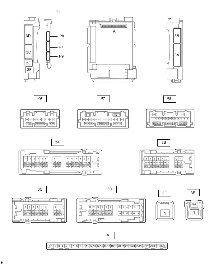
*1 Main Body ECU (Multiplex Network Body ECU) - -
-
Remove the main body ECU (multiplex network body ECU).
-
Connect the driver side junction block assembly connectors.
-
Measure the voltage and resistance according to the value(s) in the table below.
Terminal No. (Symbol) Wiring Color Terminal Description Condition Specified Condition A-31 (BECU) - Body ground None - Body ground Battery power supply Always 11 to 14 V A-30 (ACC) - Body ground None - Body ground ACC power supply Engine switch on (ACC) 11 to 14 V Engine switch off Below 1 V A-32 (IG) - Body ground None - Body ground IG power supply Engine switch on (IG) 11 to 14 V Engine switch off Below 1 V A-11 (GND1) - Body ground None - Body ground Ground Always Below 1 Ω
-
-
CHECK FRONT MULTIPLEX NETWORK DOOR ECU LH
-
Disconnect the S9 front multiplex network door ECU LH connector.

-
Measure the voltage and resistance according to the value(s) in the table below.
Tech Tips
Measure the values on the wire harness side with the connector disconnected.
Terminal No. (Symbol) Wiring Color Terminal Description Condition Specified Condition S9-1 (GND) - Body ground W-B - Body ground Ground Always Below 1 Ω S9-4 (CPUB) - Body ground LA-LG - Body ground Battery power supply Always 11 to 14 V S9-6 (BDR) - Body ground R - Body ground Battery power supply Always 11 to 14 V -
Reconnect the S9 front multiplex network door ECU LH connector.
-
Measure the voltage and resistance according to the value(s) in the table below.
Terminal No. (Symbol) Wiring Color Terminal Description Condition Specified Condition S8-1 (MRT+) - Body ground LA-B - Body ground Door outside handle sub-assembly LH (flush handle motor) opening output signal During door outside handle sub-assembly LH (flush handle motor) opening operation 11 to 14 V Door outside handle sub-assembly LH (flush handle motor) not operating Below 1 V S8-6 (MRT-) - Body ground LA-L - Body ground Door outside handle sub-assembly LH (flush handle motor) retraction output signal During door outside handle sub-assembly LH (flush handle motor) retraction operation 11 to 14 V Door outside handle sub-assembly LH (flush handle motor) not operating Below 1 V S8-10 (PS1G) - Body ground G - Body ground Door outside handle sub-assembly LH (detection switch) ground Always Below 1 Ω S8-11 (POS1) - S8-10 (PS1G) V - G Door outside handle sub-assembly LH (open position detection switch) input signal Door outside handle sub-assembly LH retracted (open position detection switch off) 11 to 14 V Door outside handle sub-assembly LH opened (open position detection switch on) Below 1 V S8-13 (LSW) - S8-10 (PS1G) BE - G Door outside handle sub-assembly LH (lock request detection switch) input signal Door outside handle sub-assembly LH depression pressed (lock request detection switch on) 11 to 14 V Door outside handle sub-assembly LH not operated (lock request detection switch off) Below 1 V S8-14 (USW) - S8-10 (PS1G) SB - G Door outside handle sub-assembly LH (unlock request detection switch) input signal Door outside handle sub-assembly LH back end pressed (unlock request detection switch on) 11 to 14 V Door outside handle sub-assembly LH not operated (unlock request detection switch off) Below 1 V
-
-
CHECK FRONT MULTIPLEX NETWORK DOOR ECU RH
-
Disconnect the R9 front multiplex network door ECU RH connector.

-
Measure the voltage and resistance according to the value(s) in the table below.
Tech Tips
Measure the values on the wire harness side with the connector disconnected.
Terminal No. (Symbol) Wiring Color Terminal Description Condition Specified Condition R9-1 (GND) - Body ground W-B - Body ground Ground Always Below 1 Ω R9-4 (CPUB) - Body ground LA-LG - Body ground Battery power supply Always 11 to 14 V R9-6 (BDR) - Body ground R - Body ground Battery power supply Always 11 to 14 V -
Reconnect the R9 front multiplex network door ECU RH connector.
-
Measure the voltage and resistance according to the value(s) in the table below.
Terminal No. (Symbol) Wiring Color Terminal Description Condition Specified Condition R8-1 (MRT+) - Body ground LA-B - Body ground Door outside handle sub-assembly RH (flush handle motor) opening output signal During door outside handle sub-assembly RH (flush handle motor) opening operation 11 to 14 V Door outside handle sub-assembly RH (flush handle motor) not operating Below 1 V R8-6 (MRT-) - Body ground LA-L - Body ground Door outside handle sub-assembly RH (flush handle motor) retraction output signal During door outside handle sub-assembly RH (flush handle motor) retraction operation 11 to 14 V Door outside handle sub-assembly RH (flush handle motor) not operating Below 1 V R8-10 (PS1G) - Body ground G - Body ground Door outside handle sub-assembly RH (detection switch) ground Always Below 1 Ω R8-11 (POS1) - R8-10 (PS1G) V - G Door outside handle sub-assembly RH (open position detection switch) input signal Door outside handle sub-assembly RH retracted (open position detection switch off) 11 to 14 V Door outside handle sub-assembly RH opened (open position detection switch on) Below 1 V R8-13 (LSW) - R8-10 (PS1G) BE - G Door outside handle sub-assembly RH (lock request detection switch) input signal Door outside handle sub-assembly RH depression pressed (lock request detection switch on) 11 to 14 V Door outside handle sub-assembly RH not operated (lock request detection switch off) Below 1 V R8-14 (USW) - R8-10 (PS1G) SB - G Door outside handle sub-assembly RH (unlock request detection switch) input signal Door outside handle sub-assembly RH back end pressed (unlock request detection switch on) 11 to 14 V Door outside handle sub-assembly RH not operated (unlock request detection switch off) Below 1 V
-