INSTRUMENT PANEL SAFETY PAD REASSEMBLY
CAUTION / NOTICE / HINT
Tech Tips
-
Use the same procedure for RHD and LHD vehicles.
-
The procedure listed below is for LHD vehicles.
PROCEDURE
-
INSTALL GLOVE COMPARTMENT DOOR LOCK CYLINDER ASSEMBLY
-
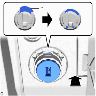
*1 Cylinder Lock 
Install in this Direction With the cylinder lock pressed, insert the glove compartment door lock cylinder assembly into the glove compartment door assembly to install it as shown in the illustration.
-
-
INSTALL GLOVE COMPARTMENT DOOR LOCK COVER
-
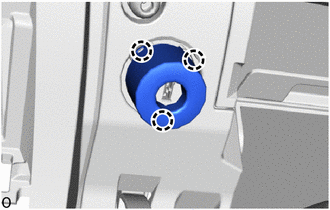
Attach the claws to install a new glove compartment door lock cover.
-
-
INSTALL NO. 1 DEFROSTER NOZZLE GARNISH
-
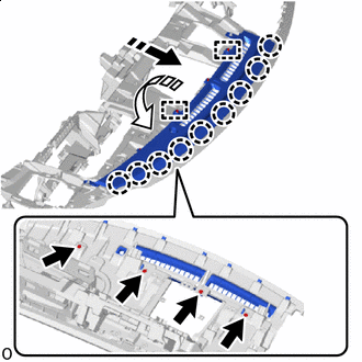
Install in this Direction (1) 
Install in this Direction (2) Align the guides and attach the claws in the direction indicated by the arrow shown in the illustration.
-
Install the No. 1 defroster nozzle garnish with the 4 screws.
-
-
INSTALL UPPER INSTRUMENT PANEL FINISH PANEL SUB-ASSEMBLY
-
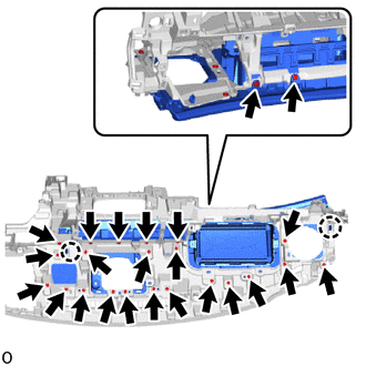
Attach the claws.
-
Install the upper instrument panel finish panel sub-assembly with the 24 screws.
-
-
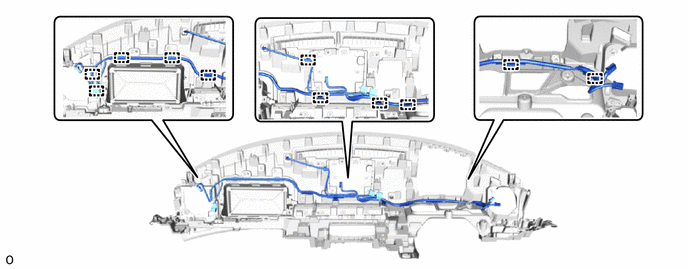
INSTALL NO. 2 INSTRUMENT PANEL WIRE
-
Attach the clamps to install the No. 2 instrument panel wire.
-
-
INSTALL NO. 1 INSTRUMENT PANEL PIN
-
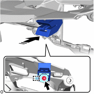
Install in this Direction Insert the guide in direction indicated by the arrow shown in the illustration.
-
Install the No. 1 instrument panel pin with the screw.
Tech Tips
Use the same procedure to install the No. 1 instrument panel pin on the other side.
-
-
INSTALL DEFROSTER NOZZLE ASSEMBLY
-
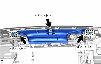
Insert the guides.
-
Install the defroster nozzle assembly with the 3 screws <F> or <H>.
-
-
INSTALL INSTRUMENT PANEL SUB-ASSEMBLY MAIN
-
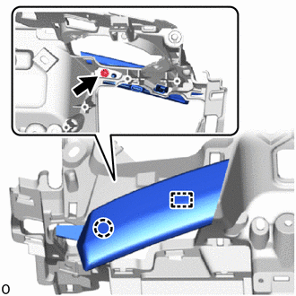
Insert the guide and attach the claw to install the instrument panel sub-assembly main.
-
Install the screw.
-
-
INSTALL FRONT NO. 2 SPEAKER ASSEMBLY
-
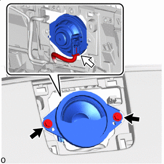

Screw 
Connector Connect the connector.
-
Install the front No. 2 speaker assembly with the 2 screws.
Note
Do not touch the cone part of the front No. 2 speaker assembly.
-
-
INSTALL NO. 1 SPEAKER OPENING COVER ASSEMBLY
-
Connect the connector.
-
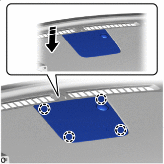
Install in this Direction Attach the claws to install the No. 1 speaker opening cover assembly.
-
-
INSTALL NO. 1 INSTRUMENT PANEL REGISTER ASSEMBLY
-
Connect the connector.
-
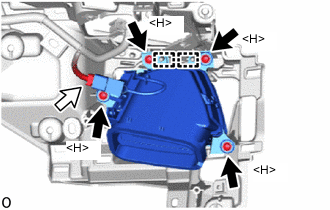
Screw Connector Insert the guides to install the No. 1 instrument panel register assembly with the 4 screws <H>.
-
-
INSTALL NO. 1 HEATER TO REGISTER DUCT
-
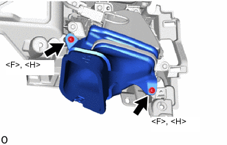
Install the No. 1 heater to register duct with the 2 screws <F> or <H>.
-
-
INSTALL AUTOMATIC LIGHT CONTROL SENSOR
-
INSTALL INSTRUMENT PANEL PASSENGER AIRBAG ASSEMBLY
-
INSTALL NAVIGATION ANTENNA ASSEMBLY WITH BRACKET
-
INSTALL NO. 3 HEATER TO REGISTER DUCT
-
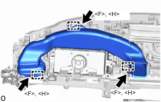
Attach the guides to install the No. 3 heater to register duct with the 3 screws <F> or <H>.
-
-
INSTALL ANTENNA CORD SUB-ASSEMBLY