FRONT EVAPORATOR TEMPERATURE SENSOR INSTALLATION
PROCEDURE
-
INSTALL NO. 1 COOLER THERMISTOR
-
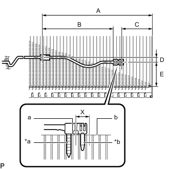
*a Fixed Part *b Sensor Part Install the No. 1 cooler thermistor as shown in the illustration.
Installation Position Part Length A 221.9 mm (8.7362 in.) B 143.6 mm (5.6535 in.) C 61.1 mm (2.4055 in.) D 10 mm (0.3937 in.) E 45 to 55 mm (1.7717 to 2.1654 in.) Note
-
Be sure to insert the No. 1 cooler thermistor only once because reinserting it into the same position will not allow it to be firmly secured.
-
When reusing the No. 1 cooler evaporator sub-assembly, insert the sensor part of the No. 1 cooler thermistor one row from the row that had been used previously (X in the illustration).
-
After inserting the No. 1 cooler thermistor, do not apply excessive force to the wire.
-
Directly insert the No. 1 cooler thermistor until the edge of the plastic case "a" comes into contact with the No. 1 cooler evaporator sub-assembly "b".
-
-
-
INSTALL NO. 1 COOLER EVAPORATOR SUB-ASSEMBLY
-
INSTALL NO. 4 AIR CONDITIONING RADIATOR DAMPER SERVO SUB-ASSEMBLY
-
INSTALL NO. 2 AIR CONDITIONING RADIATOR DAMPER SERVO SUB-ASSEMBLY
-
INSTALL NO. 1 COOLER COVER
-
INSTALL COOLER EXPANSION VALVE
-
INSTALL AIR CONDITIONING TUBE AND ACCESSORY ASSEMBLY
-
INSTALL NO. 2 COOLER COVER
-
INSTALL AIR CONDITIONING HARNESS ASSEMBLY
-
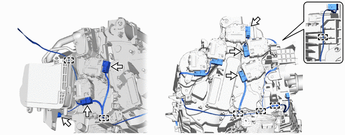
for LHD:
-
Install a portion of the air conditioning harness assembly to the guide.
-
Connect the 6 connectors.
-
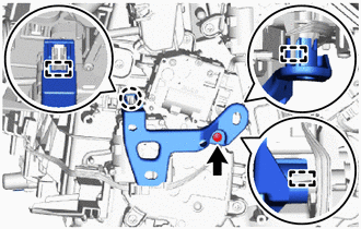
Attach the guide, guide pin and claw.
-
Install the bracket with the screw.
-
-
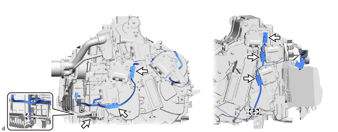
for RHD:
-
Install a portion of the air conditioning harness assembly to the guide.
-
Connect the 6 connectors.
-
-
-
INSTALL HEATER RADIATOR UNIT SUB-ASSEMBLY
-
INSTALL COOLING UNIT PARTS
-
INSTALL HEATER GROMMET
-
INSTALL BLOWER ASSEMBLY
-
INSTALL AIR CONDITIONER UNIT ASSEMBLY