COMPRESSOR REMOVAL
CAUTION / NOTICE / HINT
Tech Tips
-
Use the same procedure for RHD and LHD vehicles.
-
The procedure listed below is for LHD vehicles.
PROCEDURE
-
REMOVE NO. 1 ENGINE UNDER COVER ASSEMBLY
-
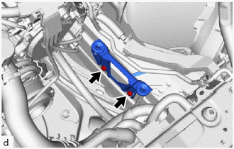
DISCONNECT FRONT STABILIZER BAR
-
REMOVE V-BANK COVER SUB-ASSEMBLY
-
RECOVER REFRIGERANT FROM REFRIGERATION SYSTEM
for HFC-134a(R134a):
for HFO-1234yf(R1234yf):
-
REMOVE RADIATOR SUPPORT TO CROSSMEMBER BRACE SUB-ASSEMBLY RH
-
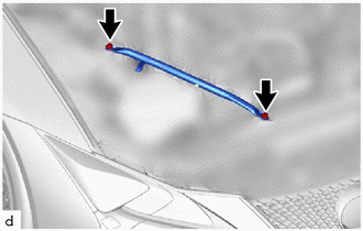
Remove the 2 bolts and radiator support to crossmember brace sub-assembly RH.
-
-
REMOVE RADIATOR SUPPORT TO CROSSMEMBER BRACE SUB-ASSEMBLY LH
-
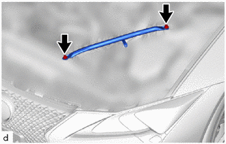
Remove the 2 bolts and radiator support to crossmember brace sub-assembly LH.
-
-
DISCONNECT NO. 2 PCV HOSE
-
DISCONNECT NO. 3 PCV HOSE
-
REMOVE AIR CLEANER HOSE ASSEMBLY
-
REMOVE AIR (WITH ELEMENT) CLEANER ASSEMBLY WITH AIR CLEANER INLET
-
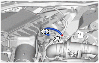
*a Connector Detach the guide.
-
Disconnect the vacuum hose from the connector.
Note
Do not apply excessive force to the vacuum hose.
-
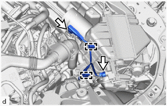
Detach the clamp.
-
Disconnect the 2 connectors.
-
Detach the clamp.
-
Disconnect the connector.
-
Remove the air (with element) cleaner assembly with air cleaner inlet from the clamp.
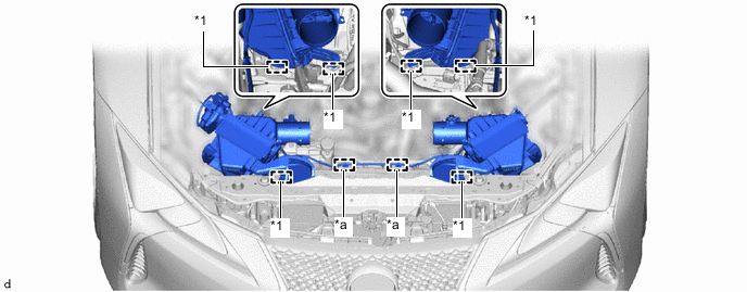
*1 Air Cleaner Support - - *a Clamp - - -
Remove the air (with element) cleaner assembly with air cleaner inlet from the air cleaner support.
Note
When removing the air (with element) cleaner assembly with air cleaner inlet, be careful not to lose the air cleaner support on the underside of the air (with element) cleaner assembly with air cleaner inlet.
-
-
REMOVE INTAKE AIR CONNECTOR PIPE
-

Bolt 
Intake Air Connector Pipe Hose Clamp Loosen the intake air connector pipe hose clamp.
-
Remove the bolt and intake air connector pipe.
-
-
REMOVE FAN AND GENERATOR V BELT
-
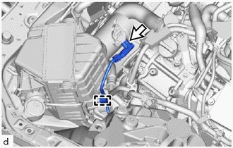
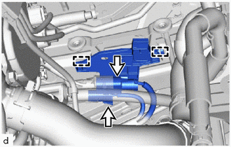
DISCONNECT SUCTION HOSE SUB-ASSEMBLY A
-
Remove the nut and disconnect the suction hose sub-assembly A from the suction tube sub-assembly B.
Note
Do not apply excessive force to the suction hose sub-assembly A and suction tube sub-assembly B.
-
Remove the O-ring from the suction hose sub-assembly A.
Note
Seal the openings of the disconnected parts using vinyl tape to prevent moisture and foreign matter from entering them.
-
-
REMOVE AIR CLEANER SUPPORT BRACKET ASSEMBLY
-
for RHD:
-
Disconnect the 2 connectors.
-
Detach the clamp and remove the No. 10 connector holder from the air cleaner support bracket assembly.
-
-
Remove the 2 bolts and air cleaner support bracket assembly.
-
-
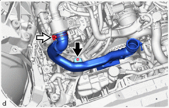
DISCONNECT DISCHARGE HOSE SUB-ASSEMBLY
-
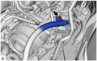
Remove the bolt and disconnect the discharge hose sub-assembly from the compressor assembly with pulley.
Note
Do not apply excessive force to the discharge hose sub-assembly.
-
Remove the O-ring from the discharge hose sub-assembly.
Note
Seal the openings of the disconnected parts using vinyl tape to prevent moisture and foreign matter from entering them.
-
-
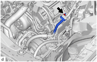
REMOVE SUCTION HOSE SUB-ASSEMBLY A
-
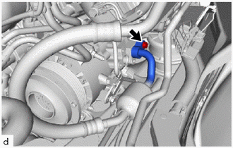
Remove the bolt and suction hose sub-assembly A from the compressor assembly with pulley.
Note
Do not apply excessive force to the suction hose sub-assembly A.
-
Remove the O-ring from the suction hose sub-assembly A.
Note
Seal the openings of the disconnected parts using vinyl tape to prevent moisture and foreign matter from entering them.
-
-
REMOVE COMPRESSOR ASSEMBLY WITH PULLEY
-
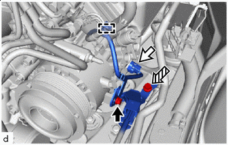
Bolt (A) Connector 
Bolt (B) Disconnect the connector.
-
Remove the bolt (A) and disconnect the wiring harness clamp bracket (bolt (A) fastening side).
-
Detach the clamp.
-
Remove the bolt (B) and disconnect the wiring harness clamp bracket (bolt (B) fastening side).
-
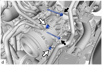
Bolt Nut Remove the 2 bolts and 2 nuts.
-
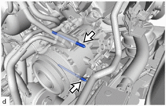
Using an E8 "TORX" socket wrench, remove the 2 stud bolts and compressor assembly with pulley.
Note
Do not drop or subject the parts to any impact.
-