FRONT AIR CONDITIONING UNIT INSTALLATION
CAUTION / NOTICE / HINT
Tech Tips
-
Use the same procedure for RHD and LHD vehicles.
-
The procedure listed below is for LHD vehicles.
-
A bolt without a torque specification is shown in the standard bolt chart.
PROCEDURE
-
INSTALL AIR CONDITIONER UNIT ASSEMBLY
-
INSTALL INSTRUMENT PANEL REINFORCEMENT ASSEMBLY
-
for LHD:
-
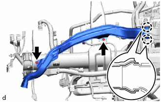
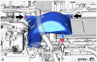
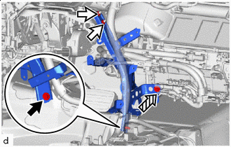
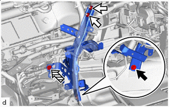
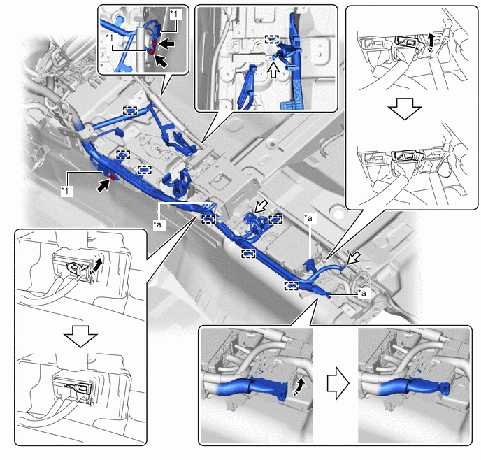
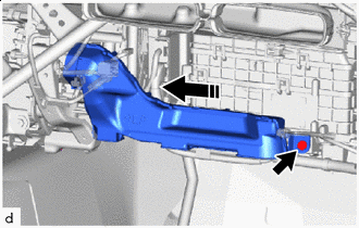
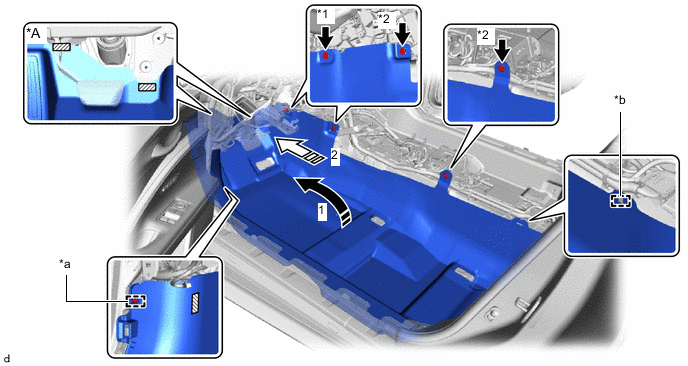
Insert the instrument panel reinforcement assembly and instrument panel wire into the application area of the air conditioner assembly as shown in the illustration.
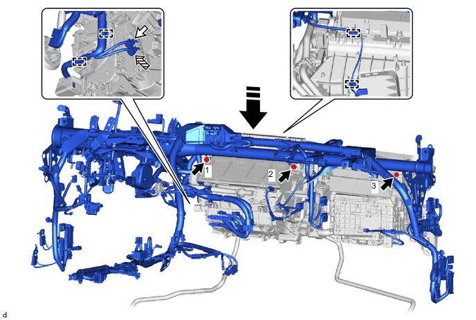

Bolt 
White Connector 
Blue Connector 
Insert Straight From Top
-
-
for RHD:
-
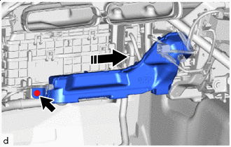
Insert the instrument panel reinforcement assembly and instrument panel wire into the application area of the air conditioner assembly as shown in the illustration.
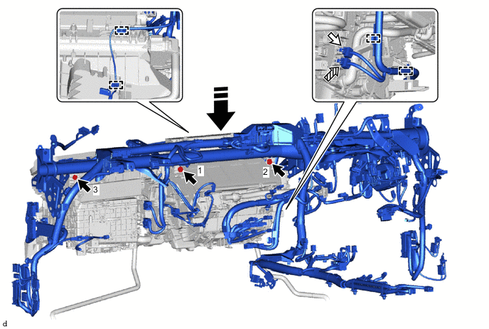
Bolt White Connector Blue Connector Insert Straight From Top
-
-
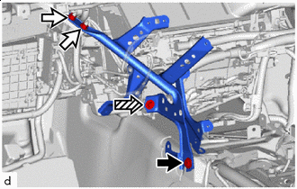
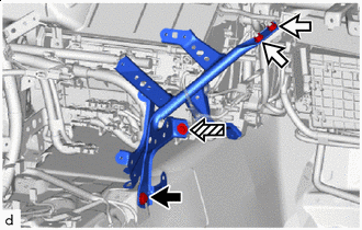
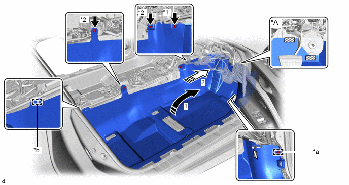
Install the 3 bolts in the order shown in the illustration.
- Torque:
- 9.8 N*m { 100 kgf*cm, 87 in.*lbf }
-
Connect the 2 connectors and attach the clamp.
Note
Connect the connectors so that the white connector is on the top side.
-
-
INSTALL LOWER DEFROSTER NOZZLE ASSEMBLY
-
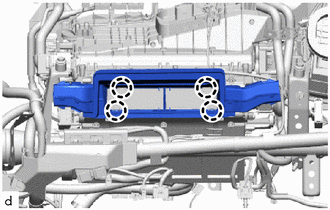
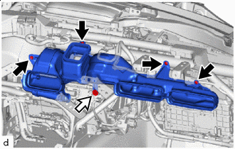
Attach the claw to install the lower defroster nozzle assembly.
-
-
INSTALL NO. 2 SIDE DEFROSTER NOZZLE DUCT
-
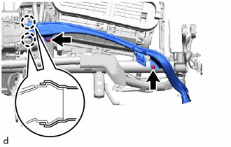
Attach the claw.
-
Install the No. 2 side defroster nozzle duct with the 2 clips.
-
-
INSTALL NO. 1 SIDE DEFROSTER NOZZLE DUCT
-
Attach the claw.
-
Install the No. 1 side defroster nozzle duct with the 2 clips.
-
-
INSTALL AIR CONDITIONING AMPLIFIER ASSEMBLY
-
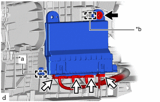
*a Guide A *b Guide B Screw Connector Insert guide A.
-
Attach guide B.
-
Install the air conditioning amplifier assembly with the screw.
-
Connect 4 connectors.
-
-
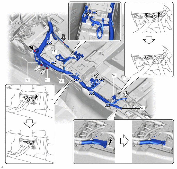
INSTALL INSTRUMENT PANEL REINFORCEMENT ASSEMBLY WITH AIR CONDITIONING UNIT ASSEMBLY
Note
-
Be sure to support the air conditioning unit assembly when installing it because failure to do so may cause the bracket of the air conditioning unit assembly to break.
-
When installing the air conditioning unit assembly, eliminate static electricity by touching the vehicle body to prevent the components from being damaged.
-
Insert the instrument panel reinforcement assembly with air conditioning unit assembly into the vehicle together with the instrument panel wire and install it to the guide as shown in the illustration.
Note
-
Be careful not to damage the internal components of the instrument panel reinforcement assembly and air conditioning unit assembly and instrument panel wire on the glass etc. Only perform installation after first taking the appropriate actions.
-
Make sure that both parts are securely installed to the guide.
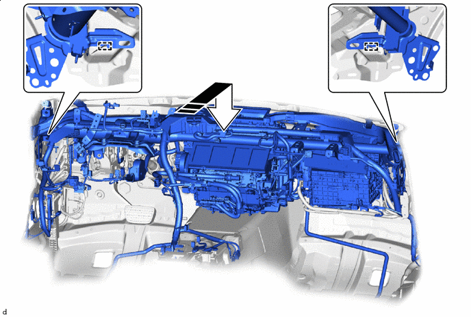
After inserting it to the end, install the guide - - -
-
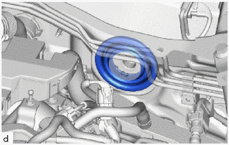
Install the cooler pipe grommet.
Note
Make sure that the dash panel is securely inserted into the groove of the cooler pipe grommet without any gaps.
-
Install the heater pipe grommet.
Note
Make sure that the dash panel is securely inserted into the groove of the heater pipe grommet without any gaps.
-
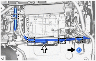
Temporarily install the 4 bolts (B) and bolt (D).
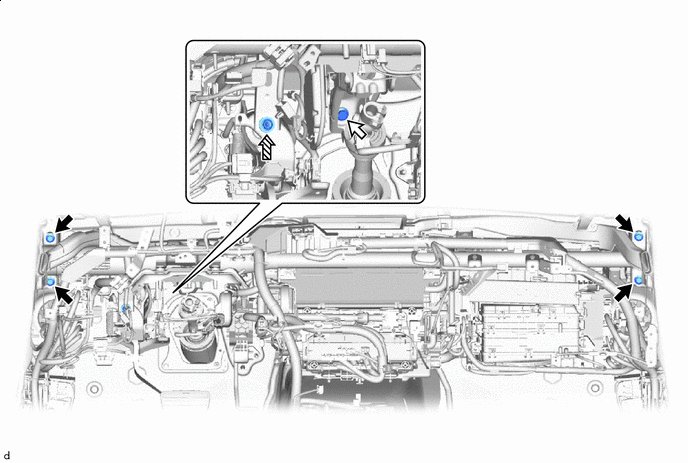
Bolt (B) Bolt (C) Bolt (D) - - -
Using a universal socket wrench 12 mm, temporarily install the bolt (C).
-
Bolt (A) Using a universal socket wrench 12 mm, temporarily install the 2 bolts (A).
-
Tighten the 4 bolts (B).
- Torque:
- 25 N*m { 255 kgf*cm, 18 ft.*lbf }
-
Using a universal socket wrench 12 mm, tighten the bolt (C) and 2 bolts (A).
- Torque:
- 25 N*m { 255 kgf*cm, 18 ft.*lbf }
-
Tighten the bolt (D).
- Torque:
- 15 N*m { 153 kgf*cm, 11 ft.*lbf }
-
Install the 3 hole plugs.
-
-
CONNECT DRAIN COOLER HOSE (for Front Passenger Side) (for LHD)
-
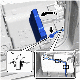
*a Start of R Turn up in this Direction Fold back part of the No. 1 floor mat and insert the drain cooler hose (for front passenger side) as shown in the illustration then and close the part of the No. 1 floor mat that was folded back.
Note
Insert the end into the grommet until the start of the R.
-
Attach the guide to the drain cooler hose (for front passenger side).
-
-
INSTALL DRAIN COOLER HOSE (for Front Passenger Side) (for RHD)
-
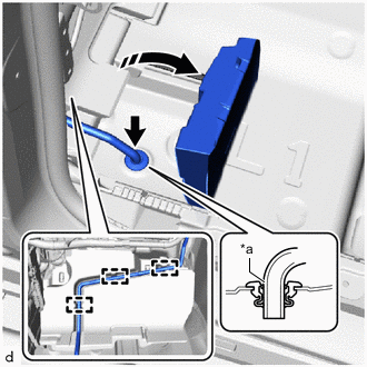
*a Start of R Turn up in this Direction Fold back part of the No. 2 floor mat and insert the drain cooler hose (for front passenger side) as shown in the illustration then and close the part of the No. 2 floor mat that was folded back.
Note
Insert the end into the grommet until the start of the R.
-
Attach the guide to the drain cooler hose (for front passenger side).
-
-
CONNECT DRAIN COOLER HOSE (for Driver's Side) (for LHD)
-
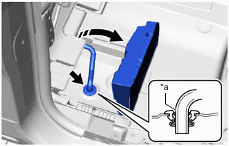
*a Start of R Turn up in this Direction Fold back part of the No. 2 floor mat and insert the drain cooler hose (for driver's side) as shown in the illustration then and close the part of the No. 2 floor mat that was folded back.
Note
Insert the end into the grommet until the start of the R.
-
-
INSTALL DRAIN COOLER HOSE (for Driver's Side) (for RHD)
-
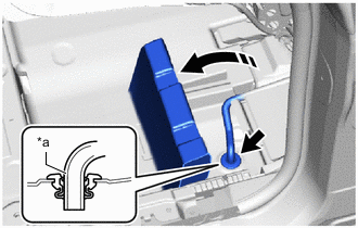
*a Start of R Turn up in this Direction Fold back part of the No. 1 floor mat and insert the drain cooler hose (for driver's side) as shown in the illustration then and close the part of the No. 1 floor mat that was folded back.
Note
Insert the end into the grommet until the start of the R.
-
-
INSTALL NO. 5 HEATER TO REGISTER DUCT
-
Clip Screw Install the No. 5 heater to register duct with the 2 clips and screw.
-
-
INSTALL NO. 1 INSTRUMENT PANEL BRACE SUB-ASSEMBLY (for LHD)
-
Bolt Nut Screw Temporarily install the No. 1 instrument panel brace sub-assembly with the 2 nuts, bolt and screw.
-
Tighten the 2 nuts and bolt.
- Torque:
- Nut
- 18 N*m { 184 kgf*cm, 13 ft.*lbf }
- Bolt
- 16 N*m { 163 kgf*cm, 12 ft.*lbf }
-
Tighten the screw.
-
-
INSTALL NO. 2 INSTRUMENT PANEL BRACE SUB-ASSEMBLY (for RHD)
-
Bolt Nut Screw Temporarily install the No. 2 instrument panel brace sub-assembly with the 2 nuts, bolt and screw.
-
Tighten the 2 nuts and bolt.
- Torque:
- Nut
- 18 N*m { 184 kgf*cm, 13 ft.*lbf }
- Bolt
- 16 N*m { 163 kgf*cm, 12 ft.*lbf }
-
Tighten the screw.
-
-
INSTALL NO. 2 INSTRUMENT PANEL BRACE SUB-ASSEMBLY (for LHD)
-
Bolt Nut Screw Temporarily install the No. 2 instrument panel brace sub-assembly with the 2 nuts, bolt and screw.
-
Tighten the 2 nuts and bolt.
- Torque:
- Nut
- 18 N*m { 184 kgf*cm, 13 ft.*lbf }
- Bolt
- 16 N*m { 163 kgf*cm, 12 ft.*lbf }
-
Tighten the screw.
-
-
INSTALL NO. 1 INSTRUMENT PANEL BRACE SUB-ASSEMBLY (for RHD)
-
Bolt Nut Screw Temporarily install the No. 1 instrument panel brace sub-assembly with the 2 nuts, bolt and screw.
-
Tighten the 2 nuts and bolt.
- Torque:
- Nut
- 18 N*m { 184 kgf*cm, 13 ft.*lbf }
- Bolt
- 16 N*m { 163 kgf*cm, 12 ft.*lbf }
-
Tighten the screw.
-
-
INSTALL NO. 3 HEATER TO REGISTER DUCT SUB-ASSEMBLY
-
Clip Screw Install the No. 3 heater to register duct sub-assembly with the 4 clips and screw.
-
-
INSTALL DRIVING SUPPORT ECU ASSEMBLY
-
INSTALL DRIVER SIDE JUNCTION BLOCK ASSEMBLY WITH MAIN BODY ECU
-
INSTALL WIRING HARNESS CLAMP BRACKET
-
Install the wiring harness clamp bracket with the screw.
-
-
INSTALL PASSENGER SIDE JUNCTION BLOCK ASSEMBLY WITH NETWORK GATEWAY ECU
-
INSTALL FRONT STEERING CONTROL ECU (w/ VGRS)
-
INSTALL SHIFT CONTROL ECU
-
INSTALL INSTRUMENT PANEL WIRE (for LHD)
-
Nut Connector Install the nut.
- Torque:
- 9.8 N*m { 100 kgf*cm, 87 in.*lbf }
-
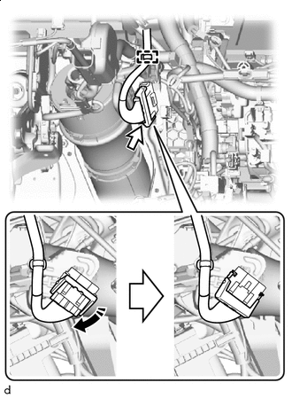
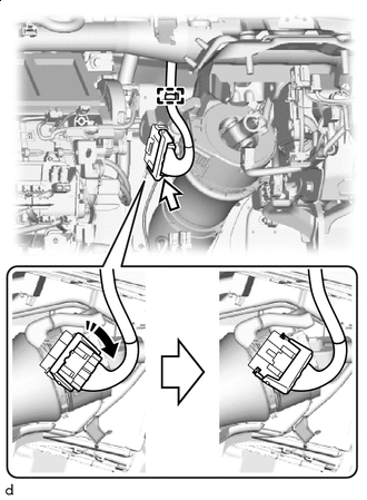
Connect the connector and attach the clamp.
-
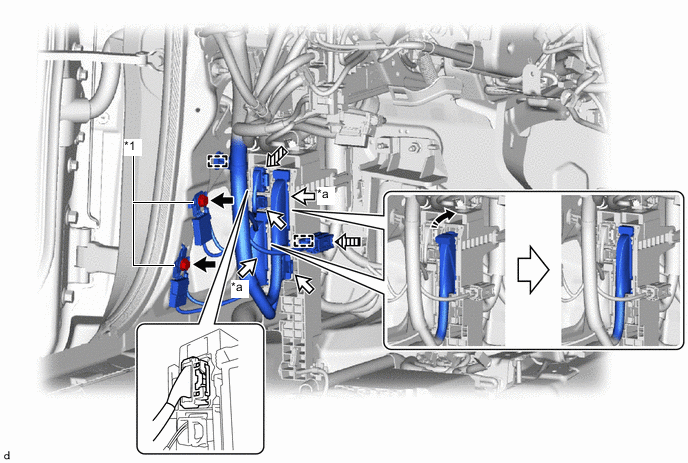
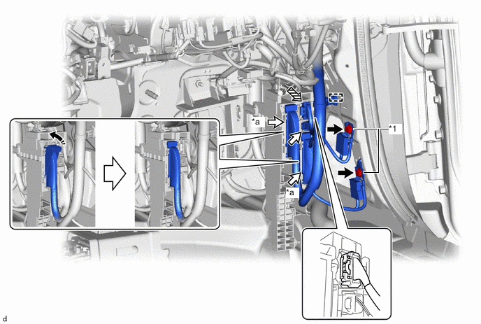
Connect the 2 ground wires with the 2 bolts.
- Torque:
- 10 N*m { 102 kgf*cm, 7 ft.*lbf }
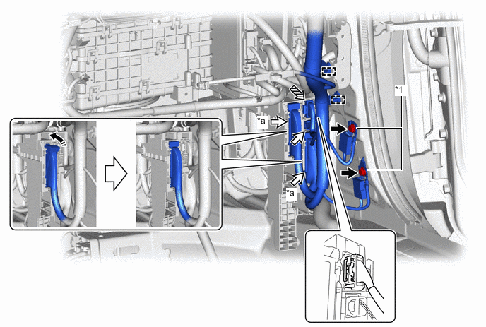
*1 Ground Wire - - *a Lever Connector - - Bolt Connector Yellow Connector Lock in this Direction -
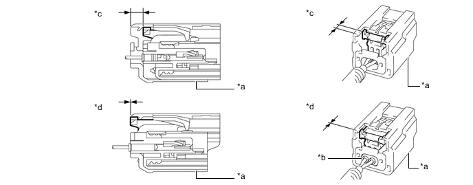
Before connecting the yellow connector, check that the CPA is positioned further back than the housing.
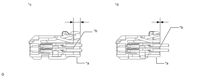
*a CPA *b Housing *c Correct *d Incorrect -
Connect the yellow connector.
-
Holding the sides of the CPA, connect it by engaging until a locking sound is heard.
Note
-
When connecting the yellow connector, press and connect it straight so as not to twist it.
-
When connecting the yellow connector, do not hold components other than the CPA.
-
Connect the connector by holding the sides of the CPA. If the upper portion of the CPA is pressed when connecting the connector, the CPA will deform and the function that prevents an incomplete connection will not operate.
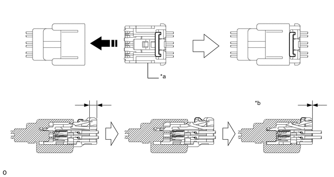
*a CPA *b Connection Complete Install in this Direction - - -
-
-
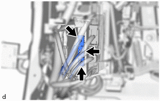
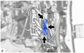
Connect the 2 lever connectors.
Note
Be sure to connect the connector securely.
-
Connect the connector and attach the clamp.
-
Connect the 3 connectors.
-
Lock in this Direction w/ VGRS:
-
Connect the connector and lock it as shown in the illustration.
Note
Be sure to connect the connector securely.
-
Attach the clamp.
-
-
Connect the 2 ground wires with the 2 bolts.
- Torque:
- 10 N*m { 102 kgf*cm, 7 ft.*lbf }
*1 Ground Wire - - *a Lever Connector - - Bolt Connector Yellow Connector (A) 
Yellow Connector (B) Lock in this direction - - -
Before connecting the yellow connector (A), check that the CPA is positioned further back than the housing.
*a CPA *b Housing *c Correct *d Incorrect -
Connect the yellow connector (A).
-
Holding the sides of the CPA, connect it by engaging until a locking sound is heard.
Note
-
When connecting the yellow connector (A), press and connect it straight so as not to twist it.
-
When connecting the yellow connector (A), do not hold components other than the CPA.
-
Connect the connector by holding the sides of the CPA. If the upper portion of the CPA is pressed when connecting the connector, the CPA will deform and the function that prevents an incomplete connection will not operate.
*a CPA *b Connection Complete Install in this Direction - - -
-
-
Before connecting the yellow connector (B), check that the CPA is positioned further back than the housing.
*a CPA *b Housing *c Correct *d Incorrect -
Connect the yellow connector (B).
-
Push while holding the sides of the CPA to connect the yellow connector.
Note
-
When connecting the yellow connector (B), press and connect it straight so as not to twist it.
-
When connecting the yellow connector (B), do not hold components other than the CPA.
-
Connect the connector by holding the sides of the CPA. If the upper portion of the CPA is pressed when connecting the connector, the CPA will deform and the function that prevents an incomplete connection will not operate.
-
-
-
Connect the 2 lever connectors.
Note
Be sure to connect the connector securely.
-
Connect the 2 connectors and attach the clamp.
-
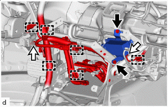
Bolt Connector Install the ion generator with bracket with the 2 bolts.
-
Connect the connector to ion generator with bracket.
-
Connect the connector and attach the clamp.
-
Connect the 3 lever connectors.
Note
Be sure to connect the connector securely.
*1 Ground Wire - - *a Lever Connector - - Bolt Connector Lock in this Direction - - -
Connect the 3 connectors.
-
Attach the clamp.
-
Connect the 3 ground wires with the 3 bolts.
- Torque:
- 10 N*m { 102 kgf*cm, 7 ft.*lbf }
-
-
INSTALL INSTRUMENT PANEL WIRE (for RHD)
-
Lock in this Direction w/ VGRS:
-
Connect the connector and lock it as shown in the illustration.
Note
Be sure to connect the connector securely.
-
Attach the clamp.
-
-
Connect the 3 connectors.
-
Connect the 2 ground wires with the 2 bolts.
- Torque:
- 10 N*m { 102 kgf*cm, 7 ft.*lbf }
*1 Ground Wire - - *a Lever Connector - - Bolt Connector Yellow Connector Lock in this Direction -
Before connecting the yellow connector, check that the CPA is positioned further back than the housing.
*a CPA *b Housing *c Correct *d Incorrect -
Connect the yellow connector.
-
Holding the sides of the CPA, connect it by engaging until a locking sound is heard.
Note
-
When connecting the yellow connector, press and connect it straight so as not to twist it.
-
When connecting the yellow connector, do not hold components other than the CPA.
-
Connect the connector by holding the sides of the CPA. If the upper portion of the CPA is pressed when connecting the connector, the CPA will deform and the function that prevents an incomplete connection will not operate.
*a CPA *b Connection Complete Install in this Direction - - -
-
-
Connect the 2 lever connectors.
Note
Be sure to connect the connector securely.
-
Connect the connector and attach the clamp.
-
Nut Connector Install the nut.
- Torque:
- 9.8 N*m { 100 kgf*cm, 87 in.*lbf }
-
Connect the connector and attach the clamp.
-
Connect the 2 ground wires with the 2 bolts.
- Torque:
- 10 N*m { 102 kgf*cm, 7 ft.*lbf }
*1 Ground Wire - - *a Lever Connector - - Bolt Connector Yellow Connector Lock in this direction -
Before connecting the yellow connector, check that the CPA is positioned further back than the housing.
*a CPA *b Housing *c Correct *d Incorrect -
Connect the yellow connector.
-
Holding the sides of the CPA, connect it by engaging until a locking sound is heard.
Note
-
When connecting the yellow connector, press and connect it straight so as not to twist it.
-
When connecting the yellow connector, do not hold components other than the CPA.
-
Connect the connector by holding the sides of the CPA. If the upper portion of the CPA is pressed when connecting the connector, the CPA will deform and the function that prevents an incomplete connection will not operate.
*a CPA *b Connection Complete Install in this Direction - - -
-
-
Connect the 2 lever connectors.
Note
Be sure to connect the connector securely.
-
Connect the 3 connectors and attach the clamp.
-
Bolt Connector Connect the connector and attach the clamp to the ion generator with bracket.
-
Install the ion generator with bracket with the 2 bolts.
-
Connect the connector and attach the clamp.
-
Connect the 3 lever connectors.
Note
Be sure to connect the connector securely.
*1 Ground Wire - - *a Lever Connector - - Bolt (A) Connector Bolt (B) Lock in this Direction -
Connect the 3 connectors.
-
Attach the clamp.
-
Connect the 3 ground wires with the 3 bolts (B).
- Torque:
- 10 N*m { 102 kgf*cm, 7 ft.*lbf }
-
Install the bolt (A).
- Torque:
- 9.8 N*m { 100 kgf*cm, 87 in.*lbf }
-
-
INSTALL TRANSMISSION FLOOR SHIFT ASSEMBLY (for LHD)
-
INSTALL NO. 2 AIR DUCT (for LHD)
-
Install in this Direction Install the No. 2 air duct with the clip.
-
-
INSTALL NO. 1 AIR DUCT (for RHD)
-
Install in this Direction Install the No. 1 air duct with the clip.
-
-
INSTALL FRONT FLOOR CARPET ASSEMBLY RH
-
Install the front floor carpet assembly RH in the order shown in the illustration.
*A for RHD - - *1 Black Clip *2 Light Gray Clip *a Clamp *b Guide Install in this Direction 
Insert to the end 
Fastener - - -
Install the front floor carpet assembly RH to the guide.
-
for LHD:
-
Attach the fastener and clamp.
-
-
for RHD:
-
Attach each fastener and clamp.
-
-
Install with the 3 clips.
-
Attach the clip to install the front floor caution plate cover.
-
-
INSTALL FRONT FLOOR CARPET ASSEMBLY LH
-
Install the front floor carpet assembly LH in the order shown in the illustration.
*A for LHD - - *1 Black Clip *2 Light Gray Clip *a Clamp *b Guide Install in this Direction Insert to the end Fastener - - -
Install the front floor carpet assembly LH to the guide.
-
for LHD:
-
Attach each fastener and clamp.
-
-
for RHD:
-
Attach the fastener and clamp.
-
-
Install with the 3 clips.
-
-
INSTALL NO. 1 SIDE TRIM BRACKET
-
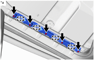
*a Left Side Align the front floor carpet assembly LH with the guide and install it to the No. 1 side trim bracket with the 5 bolts.
Tech Tips
Use the same procedure for the right side.
-
-
INSTALL ACCELERATOR PEDAL
-
INSTALL ACCELERATOR PEDAL PAD
-
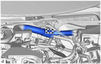
CONNECT COOLER REFRIGERANT LIQUID PIPE A
-
Remove the vinyl tape wrapped around the connection of cooler refrigerant liquid pipe A and cooler refrigerant liquid pipe A.
-
Sufficiently apply compressor oil to a new O-ring and the fitting surface of the cooler refrigerant liquid pipe A.
Compressor Oil Refrigerant Compressor Oil HFC-134a (R134a) ND-OIL 8 or equivalent HFO-1234yf (R1234yf) ND-OIL 12 or equivalent -
Install the O-ring to the cooler refrigerant liquid pipe A.
Note
Keep the O-ring and O-ring fitting surface free of foreign matter.
-
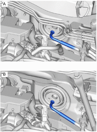
*A for LHD *B for RHD Connect the cooler refrigerant liquid pipe A.
Note
-
Do not apply excessive force to the cooler refrigerant liquid A.
-
Make sure not to cut the O-ring while installing it. (Cut O-rings cannot be installed)
-
-
-
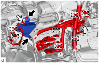
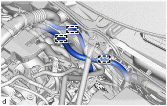
CONNECT SUCTION TUBE SUB-ASSEMBLY B
-
Remove the vinyl tape wrapped around the connection of the suction tube sub-assembly and the suction tube sub-assembly B.
-
Sufficiently apply compressor oil to a new O-ring and the fitting surface of the suction tube sub-assembly B.
Compressor Oil Refrigerant Compressor Oil HFC-134a (R134a) ND-OIL 8 or equivalent HFO-1234yf (R1234yf) ND-OIL 12 or equivalent -
Install the O-ring to the suction tube sub-assembly B.
Note
Keep the O-ring and O-ring fitting surface free of foreign matter.
-
Press in the air conditioning tube and accessory assembly until the shaft center of the pipe joint securely engages the seal hole.
Note
-
Do not apply excessive force to the suction tube sub-assembly B.
-
Make sure not to cut the O-ring while installing it. (Cut O-rings cannot be installed)
-
-
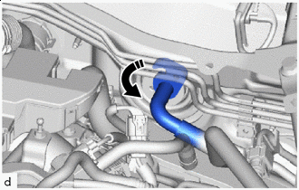
Rotate in this Direction Rotate the hook connector as shown in the illustration.
-
Install the bolt.
- Torque:
- 9.8 N*m { 100 kgf*cm, 87 in.*lbf }
-
for LHD:
-
Attach the clamp to connect the fuel emission tube sub-assembly.
-
-
for RHD:
-
Attach the clamp to connect the fuel emission tube sub-assembly.
-
Attach the clamp to connect the No. 2 engine wire.
-
Attach the clamp to connect the engine wire.
-
-
-
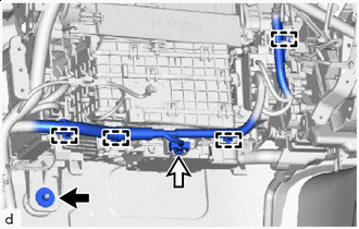
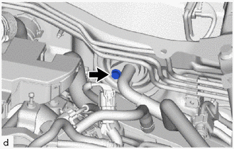
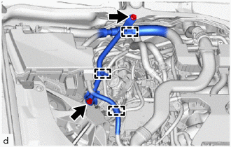
INSTALL HEATER WATER HOSE INLET
-
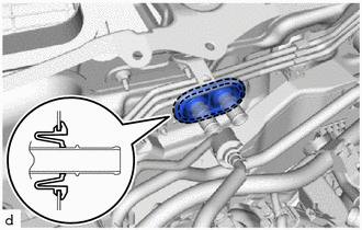
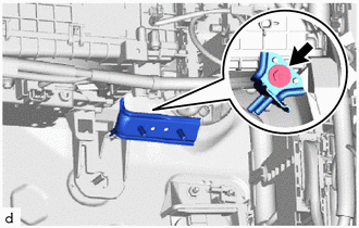
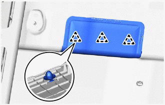
Connect with the heater water hose inlet marking (purple) facing the top of the vehicle as shown in the illustration.
Note
-
Do not apply excessive force to the heater water hose inlet.
-
Insert the heater water hose inlet until it contacts the stopper.
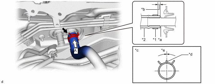
*1 Hose Clip *2 Heater Water Hose Inlet *a Stopper *b Hose Clip Installation Range (3 to 7 mm (0.1181 to 0.2756 in.)) *c View A *d Marking (Purple) *e Hose Clip Installation Angle (-15 to 15°) - - -
-
Make sure to install the 2 hose clips within the range shown in the illustration.
-
-
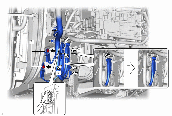
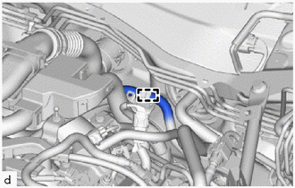
INSTALL HEATER WATER HOSE OUTLET
-
Connect with the heater water hose outlet marking (purple) facing the top of the vehicle as shown in the illustration.
Note
-
Do not apply excessive force to the heater water hose outlet.
-
Insert the heater water hose outlet until it contacts the stopper.
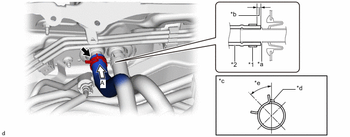
*1 Hose Clip *2 Heater Water Hose Outlet *a Stopper *b Hose Clip Installation Range (3 to 7 mm (0.1181 to 0.2756 in.)) *c View A *d Marking (Purple) *e Hose Clip Installation Angle (30 to 60°) - - -
-
Make sure to install the 2 hose clips within the range shown in the illustration.
-
-
INSTALL FENDER APRON BRACE SUB-ASSEMBLY RH (for LHD)
-
Install the fender apron brace sub-assembly RH with the 2 bolts.
- Torque:
- 49 N*m { 500 kgf*cm, 36 ft.*lbf }
-
Attach the clamp.
-
Attach the clamp to connect the engine wire.
-
-
INSTALL HEADUP DISPLAY (w/ Headup Display)
-
INSTALL INSTRUMENT PANEL SAFETY PAD SUB-ASSEMBLY
-
INSTALL STEERING COLUMN ASSEMBLY
-
INSTALL FRONT SEAT ASSEMBLY LH
-
INSTALL FRONT SEAT ASSEMBLY RH
Tech Tips
Use the same procedure as for the front seat assembly LH.
-
CONNECT CABLE TO NEGATIVE BATTERY TERMINAL
-
INSTALL NO. 2 DECK BOARD
-
INSTALL NO. 2 FRONT WIPER MOTOR AND BRACKET ASSEMBLY
-
CHARGE AIR CONDITIONING SYSTEM WITH REFRIGERANT
for HFC-134a(R134a):
for HFO-1234yf(R1234yf):
-
ADD ENGINE COOLANT
-
INSPECT FOR COOLANT LEAK
-
INSTALL NO. 2 ENGINE UNDER COVER ASSEMBLY
-
INSTALL NO. 1 ENGINE UNDER COVER ASSEMBLY
-
WARM UP ENGINE
for HFC-134a(R134a):
for HFO-1234yf(R1234yf):
-
INSPECT FOR REFRIGERANT LEAK
for HFC-134a(R134a):
for HFO-1234yf(R1234yf):
-
INSTALL V-BANK COVER SUB-ASSEMBLY
-
PERFORM DIAGNOSTIC SYSTEM CHECK
-
CHECK AND CLEAR DTC
-
INITIALIZATION SERVO MOTOR