AIR CONDITIONING SYSTEM Pressure Sensor Circuit
DESCRIPTION
If a malfunction such as fresh/recirculation mode changing without permission occurs, the following causes are possible.
| Malfunction Status | Factor |
|---|---|
|
|
WIRING DIAGRAM
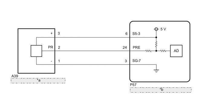
| *a | Air Conditioner Pressure Sensor |
| *b | Air Conditioning Amplifier Assembly |
PROCEDURE
-
CHECK HARNESS AND CONNECTOR (POWER SOURCE CIRCUIT)
-
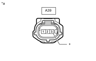
*a Front view of wire harness connector
(to Air Conditioner Pressure Sensor)
Disconnect the air conditioner pressure sensor connector.
-
Measure the voltage according to the value(s) in the table below.
Standard Voltage Tester Connection Switch Condition Specified Condition A39-3 (+) - Body ground Engine switch on (IG) 4.75 to 5.25 V Result Proceed to OK NG
NG 
CHECK HARNESS AND CONNECTOR (AIR CONDITIONING AMPLIFIER ASSEMBLY - AIR CONDITIONER PRESSURE SENSOR) Click here
OK 
-
-
CHECK HARNESS AND CONNECTOR (AIR CONDITIONER PRESSURE SENSOR - BODY GROUND)
-
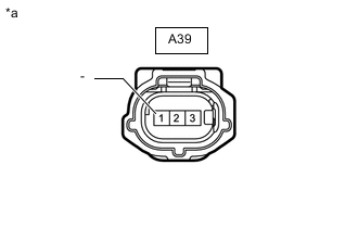
*a Front view of wire harness connector
(to Air Conditioner Pressure Sensor)
Disconnect the air conditioner pressure sensor connector.
-
Measure the resistance according to the value(s) in the table below.
Standard Resistance Tester Connection Condition Specified Condition A39-1 (-) - Body ground Always Below 1 Ω Result Proceed to OK NG
NG
CHECK HARNESS AND CONNECTOR (AIR CONDITIONING AMPLIFIER ASSEMBLY - AIR CONDITIONER PRESSURE SENSOR) Click here
OK
-
-
CHECK HARNESS AND CONNECTOR (AIR CONDITIONING AMPLIFIER ASSEMBLY - AIR CONDITIONER PRESSURE SENSOR)
-
Disconnect the P57 air conditioning amplifier assembly connector.
-
Diconnect the A39 air conditioner pressure sensor connector.
-
Measure the resistance according to the value(s) in the table below.
Standard Resistance Tester Connection Condition Specified Condition P57-24 (PRE) - A39-2 (PR) Always Below 1 Ω P57-24 (PRE) or A39-2 (PR) - Other terminals and body ground Always 10 kΩ or higher Result Proceed to OK NG
NG 
REPAIR OR REPLACE HARNESS OR CONNECTOR
OK
-
-
INSPECT AIR CONDITIONING AMPLIFIER ASSEMBLY (SENSOR SIGNAL CIRCUIT)
-
Measure the voltage when the following conditions are met.
Measurement Condition: Item Condition Vehicle doors Fully open Temperature setting MAX COLD Blower speed HI A/C switch On Recirculation/fresh switch RECIRCULATION Interior temperature 25 to 35°C (77 to 95°F) Note
-
If refrigerant pressure on the high pressure side becomes extremely high during the inspection (if the voltage exceeds 4.61 V), the fail-safe function stops compressor operation. Therefore, measure the voltage before the fail-safe operation.
-
It is necessary to measure the voltage for a certain amount of time (approximately 10 minutes) because the malfunction may recur after a while.
Tech Tips
When the outside air temperature is low (below -1.5°C (29.3°F)), the compressor stops due to operation of the thermistor assembly and the No. 1 cooler thermistor to prevent the evaporator from freezing. In this case, perform the inspection in a warm indoor environment.
-
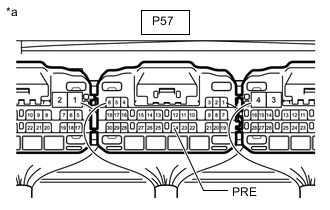
*a Component with harness connected
(Air Conditioning Amplifier Assembly)
Measure the voltage according to the value(s) in the table below.
Standard Voltage Tester Connection Switch Condition Specified Condition P57-24 (PRE) - Body ground
-
Engine switch on (IG)
-
A/C switch: On
0.62 to 4.73 V (While sensor voltage is 5 V) -
-
-
Connect the GTS to the DLC3.
-
Turn the engine switch on (IG).
-
Turn the GTS on.
-
Enter the following menus: Body Electrical / Air Conditioner / Data List.
-
Read the Data List according to the display on the GTS.
Body Electrical > Air Conditioner > Data ListTester Display Measurement Item Range Normal Condition Diagnostic Note Regulator Pressure Sensor Air conditioner pressure sensor Min.: -0.4566 MPaG
Max.: 3.2943 MPaG
Actual refrigerant pressure displayed
-
Refrigerant line (gad leak etc.)
-
Air conditioner pressure sensor system malfunction
Body Electrical > Air Conditioner > Data ListTester Display Regulator Pressure Sensor OK The voltage and value displayed in the Data List change. Result Result Proceed to OK A NG (The voltage changes but the value displayed in the Data List does not change.) NG (The voltage does not change.) B -
A
REPLACE AIR CONDITIONING AMPLIFIER ASSEMBLY Click here
B
REPLACE AIR CONDITIONER PRESSURE SENSOR Click here
-
-
CHECK HARNESS AND CONNECTOR (AIR CONDITIONING AMPLIFIER ASSEMBLY - AIR CONDITIONER PRESSURE SENSOR)
-
Disconnect the P57 air conditioning amplifier assembly connector.
-
Diconnect the A39 air conditioner pressure sensor connector.
-
Measure the resistance according to the value(s) in the table below.
Standard Resistance Tester Connection Condition Specified Condition P57-3 (SG-7) - A39-1 (-) Always Below 1 Ω P57-3 (SG-7) or A39-1 (-) - Other terminals and body ground Always 10 kΩ or higher Result Proceed to OK NG
OK
REPLACE AIR CONDITIONING AMPLIFIER ASSEMBLY Click here
NG
REPAIR OR REPLACE HARNESS OR CONNECTOR
-
-
CHECK HARNESS AND CONNECTOR (AIR CONDITIONING AMPLIFIER ASSEMBLY - AIR CONDITIONER PRESSURE SENSOR)
-
Disconnect the P57 air conditioning amplifier assembly connector.
-
Diconnect the A39 air conditioner pressure sensor connector.
-
Measure the resistance according to the value(s) in the table below.
Standard Resistance Tester Connection Condition Specified Condition P57-6 (S5-3) - A39-3 (+) Always Below 1 Ω P57-6 (S5-3) - A39-3 (+) - Other terminals and body ground Always 10 kΩ or higher Result Proceed to OK NG
OK
REPLACE AIR CONDITIONING AMPLIFIER ASSEMBLY Click here
NG
REPAIR OR REPLACE HARNESS OR CONNECTOR
-