CONDENSER INSTALLATION
CAUTION / NOTICE / HINT
Tech Tips
-
Centering bolts are used to mount the hood hinge to the vehicle body and hood. The hood cannot be adjusted with the centering bolts on. Substitute the centering bolts for standard bolts (with washers) when making adjustments.
-
A bolt without a torque specification is shown in the standard bolt chart.
-
Use the same procedure for RHD and LHD vehicles.
-
The procedure listed below is for LHD vehicles.
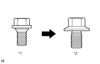
| *1 | Centering Bolt |
| *2 | Standard Bolt |
PROCEDURE
-
INSTALL COOLER CONDENSER ASSEMBLY
-
Install the sub radiator assembly to the cooler condenser assembly with the 2 bolts.
- Torque:
- 9.0 N*m { 92 kgf*cm, 80 in.*lbf }
-
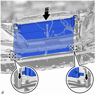

Install in the Direction Insert the cooler condenser assembly and sub radiator assembly into the vehicle and into the guide.
Note
When inserting the cooler condenser assembly and sub radiator assembly, do not damage the cooler condenser assembly, sub radiator assembly and radiator assembly.
-
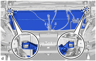
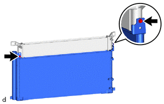
Attach the claw to install the cooler condenser assembly with sub radiator assembly.
-
-
CONNECT DISCHARGE HOSE SUB-ASSEMBLY
-
Remove the vinyl tape from the discharge hose sub-assembly and the connecting part of the cooler condenser assembly.
-
Sufficiently apply compressor oil to a new O-ring and the fitting surface of the hose joint.
Compressor Oil Refrigerant Compressor Oil HFC-134a (R134a) ND-OIL 8 or equivalent HFO-1234yf (R1234yf) ND-OIL 12 or equivalent -
Install the O-ring to the discharge hose sub-assembly.
Note
Keep the O-rings and O-ring fitting surfaces free of foreign matter.
-
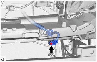
Connect the discharge hose sub-assembly to the cooler condenser assembly with the bolt.
- Torque:
- 5.4 N*m { 55 kgf*cm, 48 in.*lbf }
Note
-
Do not apply excessive force to the discharge hose sub-assembly.
-
Make sure not to cut the O-ring while installing it. (Cut O-rings cannot be installed)
-
-
CONNECT LIQUID TUBE SUB-ASSEMBLY A
-
Remove the vinyl tape from the liquid tube sub-assembly A and the connecting part of the cooler condenser assembly.
-
Sufficiently apply compressor oil to a new O-ring and the fitting surface of the tube joint.
Compressor Oil Refrigerant Compressor Oil HFC-134a (R134a) ND-OIL 8 or equivalent HFO-1234yf (R1234yf) ND-OIL 12 or equivalent -
Install the O-ring to the liquid tube sub-assembly A.
Note
Keep the O-rings and O-ring fitting surfaces free of foreign matter.
-
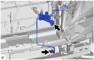
Connect the liquid tube sub-assembly A and No. 1 cooler refrigerant hose bracket to the cooler condenser assembly with the 2 bolts.
- Torque:
- 5.4 N*m { 55 kgf*cm, 48 in.*lbf }
Note
-
Do not apply excessive force to the liquid tube sub-assembly A.
-
Make sure not to cut the O-ring while installing it. (Cut O-rings cannot be installed)
-
-
CONNECT NO. 2 RADIATOR HOSE SUB-ASSEMBLY
-
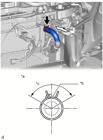
*a View A *b Marking (Yellow) *c Hose Clip Installation Angle (120°) Connect the No. 2 radiator hose sub-assembly with its marking aligned with the positioning rib as shown in the illustration and install the hose clips within the range shown in the illustration.
Note
-
Do not apply excessive force to the sub radiator assembly or No. 2 radiator hose sub-assembly.
-
Make sure the hose is securely inserted to the stopper. However, If the end of the hose is cut diagonally, it is acceptable for the entire circumference of the tip to not contact the stopper.
-
Install the hose clips 2 to 5 mm (0.0787 to 0.1969 in.) away from the end of the hose.
-
-
-
CONNECT RADIATOR HOSE SUB-ASSEMBLY
-
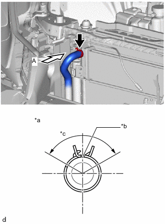
*a View A *b Marking (Yellow) *c Hose Clip Installation Angle (120°) Connect the radiator hose sub-assembly with its marking aligned with the positioning rib as shown in the illustration and install the hose clips within the range shown in the illustration.
Note
-
Do not apply excessive force to the sub radiator assembly or radiator hose sub-assembly.
-
Make sure the hose is securely inserted to the stopper. However, If the end of the hose is cut diagonally, it is acceptable for the entire circumference of the tip to not contact the stopper.
-
Install the hose clips 2 to 5 mm (0.0787 to 0.1969 in.) away from the end of the hose.
-
-
-
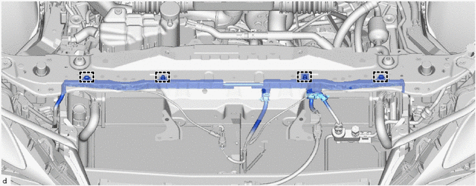
INSTALL UPPER RADIATOR SUPPORT
-
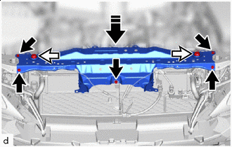

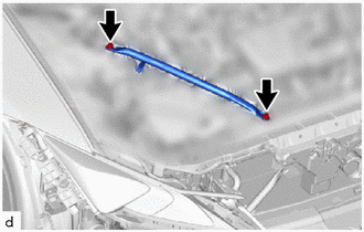
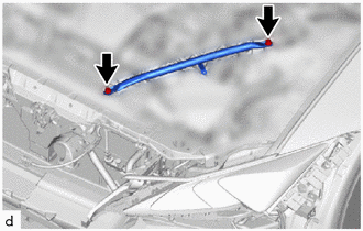
Bolt 
Radiator Support Cushion Install in this Direction Attach the upper radiator support to the 2 radiator support cushions and install the upper radiator support with the 5 bolts as shown in the illustration.
- Torque:
- 12.5 N*m { 127 kgf*cm, 9 ft.*lbf }
Note
When installing the upper radiator support, do not damage the cooler condenser assembly, sub radiator assembly and radiator assembly.
-
for LHD:
-
Attach the clamp to connect the engine room main wire.
-
-
for RHD:
-

Attach the clamp to connect the engine room main wire.
-
-
-
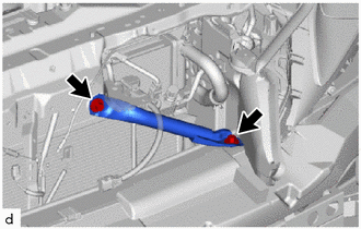
INSTALL LOWER ARM BRACKET BRACE SUB-ASSEMBLY RH
-
Install the lower arm bracket brace sub-assembly RH with the 2 bolts.
- Torque:
- 20 N*m { 204 kgf*cm, 15 ft.*lbf }
-
-
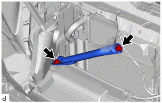
INSTALL LOWER ARM BRACKET BRACE SUB-ASSEMBLY LH
-
Install the lower arm bracket brace sub-assembly LH with the 2 bolts.
- Torque:
- 20 N*m { 204 kgf*cm, 15 ft.*lbf }
-
-
INSTALL LOW PITCHED HORN ASSEMBLY
-
INSTALL HOOD LOCK ASSEMBLY
-
INSTALL HOOD LOCK CONTROL CABLE COVER LH (for LHD)
-
INSTALL HOOD LOCK CONTROL CABLE COVER RH
-
Attach the clamp and install the hood lock control cable cover RH.
-
-
INSTALL AIR (WITH ELEMENT) CLEANER ASSEMBLY WITH AIR CLEANER INLET
Note
Check that the air cleaner support is properly installed to the specified position on the air cleaner support bracket and upper radiator support.
-
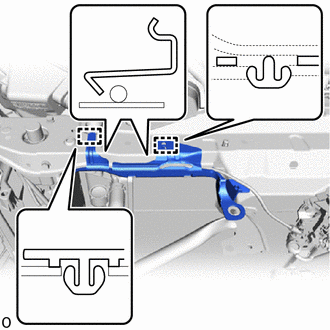
Install the air (with element) cleaner assembly with air cleaner inlet to the air cleaner support.
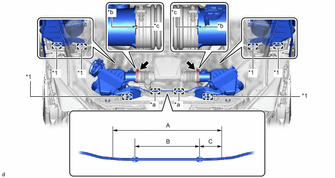
*1 Air Cleaner Support - - *a Clamp *b Protrusion *c Cutout - - No. 2 Air Cleaner Hose Clamp - - -
Attach the clamp as shown in the illustration.
Installation Position Part Length A 310 mm (1.02 ft.) B 176 to 186 mm (6.9291 to 7.3228 in.) C 60.5 to 68.5 mm (2.3819 to 2.6968 in.) -
Align the cutout of the No. 2 air cleaner hose with the protrusion of the air (with element) cleaner assembly with air cleaner inlet and connect the air (with element) cleaner assembly with air cleaner inlet as shown in the illustration.
Note
Insert the air (with element) cleaner assembly with air cleaner inlet until it hits the stopper.
-
Tighten the No. 2 air cleaner hose clamp as shown in the illustration.
Note
Install the intake No. 2 air cleaner hose clamp so that it contacts the No. 2 air cleaner hose positioning stopper.
- Torque:
- 4.0 N*m { 41 kgf*cm, 35 in.*lbf }
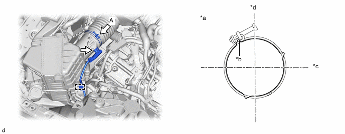
*a View A *b Positioning Stopper *c Front of Vehicle *d Top of Vehicle -
Connect the connector.
-
Attach the clamp.
-
Tighten the No. 2 air cleaner hose clamp as shown in the illustration.
Note
Install the intake No. 2 air cleaner hose clamp so that it contacts the No. 2 air cleaner hose positioning stopper.
- Torque:
- 4.0 N*m { 41 kgf*cm, 35 in.*lbf }
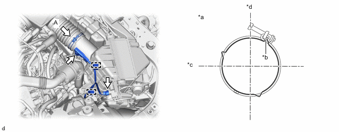
*a View A *b Positioning Stopper *c Front of Vehicle *d Top of Vehicle -
Connect the 2 connectors.
-
Attach the clamp.
-
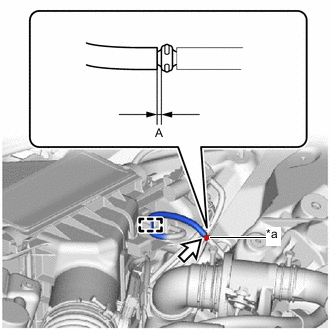
*a Connector Connect the vacuum hose to the connector as shown in the illustration.
Installation Position Part Length A 2 mm (0.0787 in.) or less. -
Install the vacuum hose to the guide.
-
-
INSTALL RADIATOR SUPPORT TO CROSSMEMBER BRACE SUB-ASSEMBLY RH
-
Install the radiator support to crossmember brace sub-assembly RH with the 2 bolts.
- Torque:
- 49 N*m { 500 kgf*cm, 36 ft.*lbf }
-
-
INSTALL RADIATOR SUPPORT TO CROSSMEMBER BRACE SUB-ASSEMBLY LH
-
Install the radiator support to crossmember brace sub-assembly LH with the 2 bolts.
- Torque:
- 49 N*m { 500 kgf*cm, 36 ft.*lbf }
-
-
CHARGE AIR CONDITIONING SYSTEM WITH REFRIGERANT
for HFC-134a(R134a):
for HFO-1234yf(R1234yf):
-
ADD ENGINE COOLANT
-
INSPECT FOR COOLANT LEAK
-
INSTALL FRONT BUMPER ASSEMBLY
-
INSTALL NO. 2 ENGINE UNDER COVER ASSEMBLY
-
INSTALL NO. 1 ENGINE UNDER COVER ASSEMBLY
-
INSPECT FITTING OF HOOD SUB-ASSEMBLY
-
ADJUST HOOD SUB-ASSEMBLY
-
INSTALL HOOD LOCK RELEASE LEVER PROTECTOR
-
WARM UP ENGINE
for HFC-134a(R134a):
for HFO-1234yf(R1234yf):
-
INSPECT FOR REFRIGERANT LEAK
for HFC-134a(R134a):
for HFO-1234yf(R1234yf):
-
INSTALL V-BANK COVER SUB-ASSEMBLY