AIR CONDITIONING SYSTEM, Diagnostic DTC:B1451
| DTC Code | DTC Name |
|---|---|
| B1451 | Compressor Solenoid Circuit |
DESCRIPTION
In this circuit, the compressor assembly with pulley receives a refrigerant compression demand signal from the air conditioning amplifier assembly. Based on this signal, the compressor assembly with pulley changes the amount of compressor output.
| DTC No. | Detection Item | DTC Detection Condition | Trouble Area | Memory |
|---|---|---|---|---|
| B1451 | Compressor Solenoid Circuit |
|
|
Memorized |
WIRING DIAGRAM
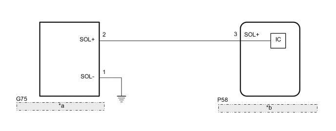
| *a | Compressor Assembly with Pulley |
| *b | Air Conditioning Amplifier Assembly |
PROCEDURE
-
PERFORM ACTIVE TEST USING GTS (COMPRESSOR SOLENOID)
-
Connect the GTS to the DLC3.
-
Turn the engine switch on (IG).
-
Turn the GTS on.
-
Enter the following menus: Body Electrical / Air Conditioner / Active Test.
-
Check the operation by referring to the table below.
Body Electrical > Air Conditioner > Data ListTester Display Measurement Item Range Normal Condition Diagnostic Note Regulator Control Current Solenoid valve control current Min.: 0 A
Max.: 0.997 A
Solenoid valve control current Compressor system malfunction
Body Electrical > Air Conditioner > Data ListTester Display Regulator Control Current OK The display is as specified in the normal condition column. Result Proceed to OK NG
OK 
REPLACE AIR CONDITIONING AMPLIFIER ASSEMBLY Click here
NG 
-
-
INSPECT COMPRESSOR ASSEMBLY WITH PULLEY
-
Remove the compressor assembly with pulley.
-
Inspect the compressor assembly with pulley.
Result Proceed to OK NG
NG
REPLACE COMPRESSOR ASSEMBLY WITH PULLEY Click here
OK
-
-
CHECK HARNESS AND CONNECTOR (COMPRESSOR ASSEMBLY WITH PULLEY - AIR CONDITIONING AMPLIFIER ASSEMBLY AND BODY GROUND)
-
Disconnect the G75 compressor assembly with pulley connector.
-
Disconnect the P58 air conditioning amplifier assembly connector.
-
Measure the resistance according to the value(s) in the table below.
Standard Resistance Tester Connection Condition Specified Condition G75-2 (SOL+) - P58-3 (SOL+) Always Below 1 Ω G75-2 (SOL-) - body ground Always Below 1 Ω G75-2 (SOL+) or P58-3 (SOL+) - Other terminals and body ground Always 10 kΩ or higher Result Proceed to OK NG
OK
REPLACE AIR CONDITIONING AMPLIFIER ASSEMBLY Click here
NG
REPAIR OR REPLACE HARNESS OR CONNECTOR
-