AIR CONDITIONING SYSTEM, Diagnostic DTC:B14B2
| DTC Code | DTC Name |
|---|---|
| B14B2 | Lost Communication with Front Panel LIN |
DESCRIPTION
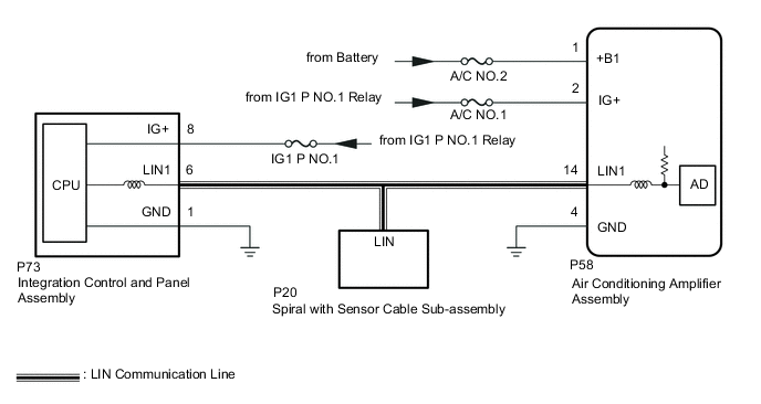
The air conditioning control assembly communicates with the air conditioning amplifier assembly via LIN communication.
If the LIN communication system malfunctions, the air conditioning amplifier assembly does not operate even if the air conditioning control assembly is operated.
| DTC No. | Detection Item | DTC Detection Condition | Trouble Area | Memory |
|---|---|---|---|---|
| B14B2 | Lost Communication with Front Panel LIN | Lost communication with air conditioning control assembly
|
|
Memorized |
WIRING DIAGRAM
CAUTION / NOTICE / HINT
Note
-
Inspect the fuses for circuits related to this system before performing the following procedure.
-
If DTC B14B2 and B14B7 are output at the same time, troubleshoot for DTC B14B7 first.
-
The vehicle is equipped with a Supplemental Restraint System (SRS) which includes components such as airbags. Before servicing (including removal or installation of parts), be sure to read the precaution for Supplemental Restraint System.
PROCEDURE
-
CHECK HARNESS AND CONNECTOR (INTEGRATION CONTROL AND PANEL ASSEMBLY - BATTERY AND BODY GROUND)
-
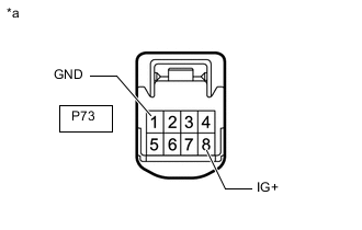
*a Front view of wire harness connector
(to Integration Control and Panel Assembly)
Disconnect the integration control and panel assembly connector.
-
Measure the resistance according to the value(s) in the table below.
Standard Resistance Tester Connection Condition Specified Condition P73-1 (GND) - Body ground Always Below 1 Ω -
Measure the voltage according to the value(s) in the table below.
Standard Voltage Tester Connection Switch Condition Specified Condition P73-8 (IG+) - Body ground Engine switch on (IG) 11 to 14 V Engine switch off Below 1 V Result Proceed to OK NG
NG 
REPAIR OR REPLACE HARNESS OR CONNECTOR
OK 
-
-
CHECK HARNESS AND CONNECTOR (AIR CONDITIONING AMPLIFIER ASSEMBLY - AIR CONDITIONING CONTROL ASSEMBLY)
-
Disconnect the P58 air conditioning amplifier assembly connector.
-
Disconnect the P73 integration control and panel assembly connector.
-
Disconnect the P20 spiral with sensor cable sub-assembly connector.
-
Measure the resistance according to the value(s) in the table below.
Standard Resistance Tester Connection Condition Specified Condition P58-14 (LIN1) - P73-6 (LIN1) Always Below 1 Ω P58-14 (LIN1) or P73-6 (LIN1) - Other terminals and body ground Always 10 kΩ or higher Result Proceed to OK NG
NG
REPAIR OR REPLACE HARNESS OR CONNECTOR
OK
-
-
CHECK AIR CONDITIONING AMPLIFIER ASSEMBLY (OUTPUT SIGNAL)
-
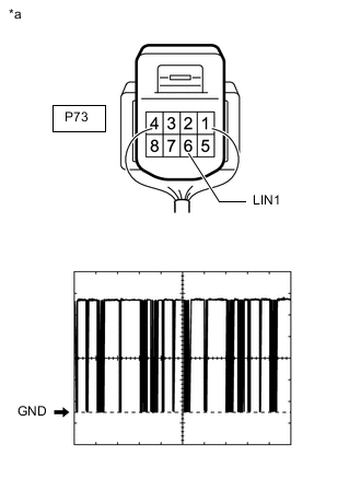
*a Component with harness connected
(Integration Control and Panel Assembly)
Using an oscilloscope, check the waveform.
Item Content Tester Connection P73-6 (LIN1) - Body ground Tool Setting 2 V/DIV., 20 ms/DIV. Condition Engine switch on (IG) OK The waveform displays properly. Result Proceed to OK NG
NG
REPLACE AIR CONDITIONING AMPLIFIER ASSEMBLY Click here
OK
-
-
CHECK INTEGRATION CONTROL AND PANEL ASSEMBLY (OUTPUT SIGNAL)
-
Using an oscilloscope, check the waveform.
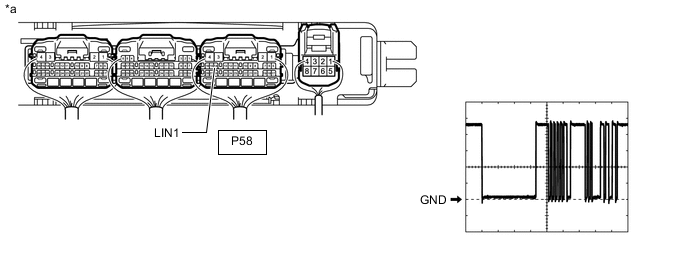
*a Component with harness connected
(Air Conditioning Amplifier Assembly)
- - Item Content Tester Connection P58-14 (LIN1) - Body ground Tool Setting 2 V/DIV., 20 ms/DIV. Condition Engine switch on (IG) OK The waveform displays properly. Result Proceed to OK NG
OK
REPLACE AIR CONDITIONING AMPLIFIER ASSEMBLY Click here
NG
REPLACE INTEGRATION CONTROL AND PANEL ASSEMBLY (AIR CONDITIONING CONTROL ASSEMBLY WAS DEFECTIVE) Click here
-