LUMBAR SUPPORT ADJUSTER ASSEMBLY REMOVAL
CAUTION / NOTICE / HINT
The necessary procedures (adjustment, calibration, initialization or registration) that must be performed after parts are removed, installed or replaced during the lumbar support adjuster assembly LH removal/installation are shown below.
| Replacement Part or Procedure | Necessary Procedures | Effects / Inoperative when not Performed | Link |
|---|---|---|---|
| Disconnect cable from negative battery terminal | Memorize steering angle neutral point | LKA/LDA system | |
| Pre-collision system | |||
| Parking assist monitor system | |||
| Steering sensor zero point calibration | Variable gear ratio steering system | ||
|
Initialize position control ECU | Front Power Seat Control System |
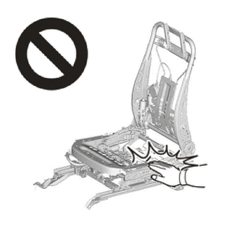
CAUTION:
-
Wear protective gloves. Sharp areas on the parts may injure your hands.
-
There is risk of injury.
Tech Tips
-
Use the same procedure for RHD and LHD vehicles.
-
The procedure listed below is for LHD vehicles.
-
Use the same procedure for the RH side and LH side.
-
The following procedure is for the LH side.
PROCEDURE
-
PRECAUTION
Note
After turning the engine switch off, waiting time may be required before disconnecting the cable from the negative (-) battery terminal. Therefore, make sure to read the disconnecting the cable from the negative (-) battery terminal notice before proceeding with work.
-
REMOVE FRONT SEAT ASSEMBLY LH
-
REMOVE FRONT SEAT CUSHION SHIELD LH
-
REMOVE FRONT INNER SEAT CUSHION SHIELD LH
-
REMOVE LIMIT SWITCH ASSEMBLY
-
REMOVE SEPARATE TYPE FRONT SEATBACK ASSEMBLY
-
REMOVE SEAT ADJUSTER COVER CAP LH
-
REMOVE RECLINING REMOTE CONTROL LEVER SUB-ASSEMBLY LH
-
REMOVE FRONT SEATBACK SUB-ASSEMBLY LH (for Standard Seat Type)
-
REMOVE FRONT SEAT HEADREST SUPPORT (for Standard Seat Type)
-
REMOVE FRONT SEAT HEADREST SUPPORT (for Sports Seat Type)
-
REMOVE FRONT UPPER SEATBACK COVER SUB-ASSEMBLY LH (for Standard Seat Type)
-
REMOVE SEPARATE TYPE FRONT SEATBACK COVER WITH PAD (for Standard Seat Type)
-
REMOVE FRONT SEATBACK PAD WITH COVER LH (for Sports Seat Type)
-
REMOVE SEATBACK CLIMATE CONTROL BLOWER LH
-
REMOVE LUMBAR SUPPORT ADJUSTER ASSEMBLY LH
-
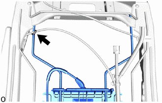
Cut off the cable tie.
-
Detach the wire harness clamps and disconnect the connector.
-
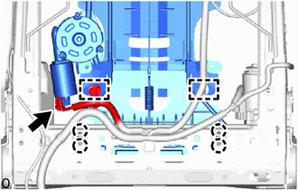
Detach the claws.
-

Remove in this Direction 
Protective Tape Using a screwdriver, detach the claws.
Tech Tips
Tape the screwdriver tip before use.
Note
If the claw of the front seatback hook is detached, replace the front seatback hook with a new one.
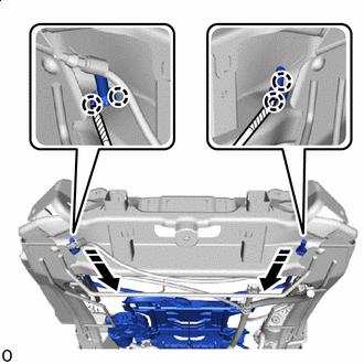
-
Slide in the removal direction shown in the illustration and remove the lumbar support adjuster assembly LH together with the 2 front seatback hooks and 2 front seatback edge protectors.
-
-
REMOVE FRONT SEATBACK HOOK
-
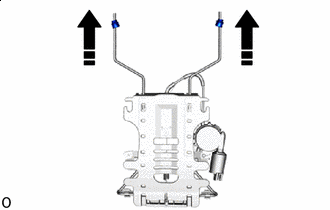
Remove in this Direction Pull in the removal direction shown in the illustration to remove the 2 front seatback hooks.
Note
Do not reuse the front seatback hook after removing it.
-
-
REMOVE FRONT SEATBACK EDGE PROTECTOR
-
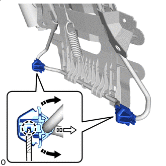
Remove in this Direction (1) 
Remove in this Direction (2) Protective Tape Using a screwdriver, detach the claws.
Tech Tips
Tape the screwdriver tip before use.
-
Pull in the removal direction (1) shown in the illustration to open the front seatback edge protector.
-
Pull in the removal direction (2) shown in the illustration to remove the front seatback edge protector.
Tech Tips
Use the same procedure for both of the front seatback edge protector.
-