SEAT HEATER SYSTEM TERMINALS OF ECU
-
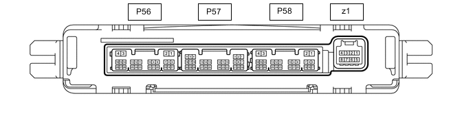
CHECK AIR CONDITIONING AMPLIFIER ASSEMBLY
-
Disconnect the P58 air conditioning amplifier assembly connector.
-
Measure the voltage and resistance according to the value(s) in the table below.
Terminal No. (Symbol) Wiring Color Terminal Description Condition Specified Condition P58-2 (IG+) - Body ground R - Body ground IG power supply Engine switch on (IG) 11 to 14 V Engine switch off Below 1 V P58-4 (GND) - Body ground W-B - Body ground Ground Always Below 1 Ω -
Reconnect the P58 air conditioning amplifier assembly connector.
-
Measure the voltage and resistance according to the value(s) in the table below.
Terminal No. (Symbol) Wiring Color Terminal Description Condition Specified Condition P56-15 (SHD+) - Body ground P - Body ground Seat heater switch (for LH) volume signal
-
Engine switch on (IG)
-
Seat heater switch (for LH) on: (LO)
Below 1 V P58-16 (SHP+) - Body ground L - Body ground Seat heater switch (for RH) volume signal
-
Engine switch on (IG)
-
Refreshing seat switch on (LO)
Seat heater switch (for RH): on (LO)
Below 1 V P56-17 (TSL) - Body ground B - Body ground Seat heater sensor (for LH) input signal Engine switch off
(0 to 30°C [32 to 86°F])
26.74 to 8.41 kΩ P56-18 (TSR) - Body ground G - Body ground Seat heater sensor (for RH) input signal Engine switch off
(0 to 30°C [32 to 86°F])
26.74 to 8.41 kΩ P57-8 (SG-5) - Body ground LG - Body ground Sensor ground Always Below 1 Ω P56-9 (SG-6) - Body ground R - Body ground Sensor ground Always Below 1 Ω -
-
-
CHECK RADIO RECEIVER ASSEMBLY