FRONT SEAT ASSEMBLY REMOVAL

CAUTION / NOTICE / HINT
The necessary procedures (adjustment, calibration, initialization or registration) that must be performed after parts are removed, installed or replaced during the front seat assembly LH removal/installation are shown below.
| Replacement Part or Procedure | Necessary Procedures | Effects / Inoperative when not Performed | Link |
|---|---|---|---|
| Disconnect cable from negative battery terminal | Memorize steering angle neutral point | LKA/LDA system | |
| Pre-collision system | |||
| Parking assist monitor system | |||
| Steering sensor zero point calibration | Variable gear ratio steering system | ||
|
Initialize position control ECU | Front Power Seat Control System |
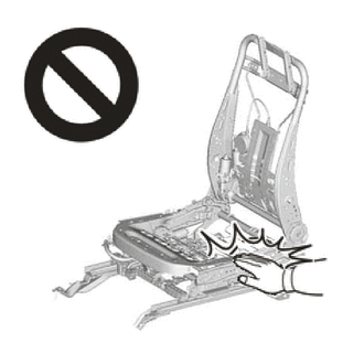
CAUTION:
-
Wear protective gloves. Sharp areas on the parts may injure your hands.
-
There is risk of injury.
Note
-
If the front seat airbag assembly LH was deployed, replace the front seat airbag assembly LH, front seatback frame sub-assembly LH, separate type front seatback pad, separate type front seatback cover and front seatback sub-assembly LH with the necessary parts in accordance with the extent of the collision damage.
-
Replace any other damaged parts as necessary.
for Standard Seat Type:
-
If the front seat airbag assembly LH was deployed, replace the front seat airbag assembly LH, front seatback frame sub-assembly LH and front seatback pad with cover LH with the necessary parts in accordance with the extent of the collision damage.
-
Replace any other damaged parts as necessary.
for Sports Seat Type:
Tech Tips
-
Use the same procedure for RHD and LHD vehicles.
-
The procedure listed below is for LHD vehicles.
-
Use the same procedure for the RH side and LH side.
-
The following procedure is for the LH side.
PROCEDURE
-
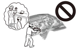
PRECAUTION
CAUTION:
Some of these service operations affect the SRS airbag system. Read the precautionary notices concerning the SRS airbag system before servicing.
Note
After turning the engine switch off, waiting time may be required before disconnecting the cable from the negative (-) battery terminal. Therefore, make sure to read the disconnecting the cable from the negative (-) battery terminal notice before proceeding with work.
-
CUSTOMIZE POWER TILT AND POWER TELESCOPIC STEERING COLUMN SYSTEM
-
Disable the auto tilt away function by changing the customize parameter.
Note
Record the current customize parameter setting (whether the auto tilt away function is enabled or disabled) in order to restore the current setting after finishing the operation.
Tech Tips
Performing the above operation causes the auto tilt away function to be disabled when the engine switch is turned off.
-
Turn the engine switch on (IG). Operate the tilt and telescopic switch to fully retract and tilt up the steering column assembly.
-
Turn the engine switch off.
-
-
REMOVE NO. 2 DECK BOARD
-
REMOVE FRONT SEAT HEADREST ASSEMBLY
-
for Standard Seat Type:
-
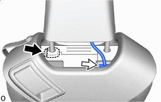

Lock Release Knob 
Connector While pressing the lock release knob from the top of the front upper seatback cover sub-assembly LH, gently lift up the front seat headrest assembly.
Tech Tips
As the lock release knob is positioned underneath the front upper seatback cover sub-assembly it cannot be visually checked. Therefore, insert a finger from the top of the front upper seatback cover sub-assembly as shown in the illustration to release the lock.
-
Stop midway and disconnect the connector of the front seat headrest assembly.
Note
If the front seat headrest assembly is lifted up too far before disconnecting the connector, the wire harness may be damaged.
-
While pressing the lock release knob from the top of the front upper seatback cover sub-assembly LH, lift up the front seat headrest assembly to the end and remove it.
-
-
for Sport Seat Type:
-
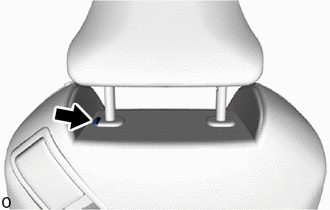
While pressing the lock release knob, lift up the front seat headrest assembly and remove it.
-
-
-
REMOVE OUTER SEAT TRACK COVER LH
-
Operate the slide and vertical power seat switch knob to slide the front seat assembly LH to the frontmost position.
-
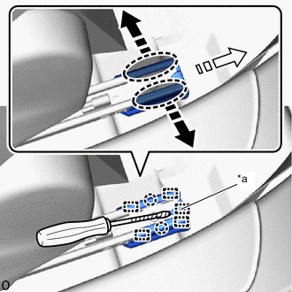
*a Guide Pin 
Place Hand Here 
Remove in this Direction (1) 
Remove in this Direction (2) 
Protective Tape Using a thin-bladed screwdriver, detach the guide pin.
Tech Tips
Tape the thin-bladed screwdriver tip before use.
-
Place your hands at the positions shown in the illustration and pull in the removal direction (1) to detach the claws.
-
Slide in the removal direction (2) to detach the guides and remove the outer seat track cover LH.
-
-
REMOVE INNER SEAT TRACK BRACKET COVER LH
-
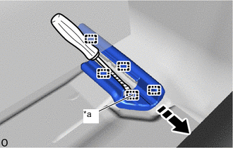
*a Guide Pin Remove in this Direction Protective Tape Using a thin-bladed screwdriver, detach the guide pin.
Tech Tips
Tape the thin-bladed screwdriver tip before use.
-
Slide in the removal direction shown in the illustration, detach the guides and remove the inner seat track bracket cover LH.
-
-
REMOVE FRONT OUTER SEAT TRACK BRACKET COVER LH
-
Operate the slide and vertical power seat switch knob to slide the front seat assembly LH to the rearmost position.
-
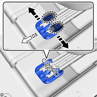
Place Hand Here Remove in this Direction (1) Remove in this Direction (2) Place your hands at the positions shown in the illustration and pull in the removal direction (1) to detach the claws.
-
Slide in the removal direction (2) to detach the guides and remove the front outer seat track bracket cover LH.
-
-
REMOVE FRONT INNER SEAT TRACK BRACKET COVER LH
-
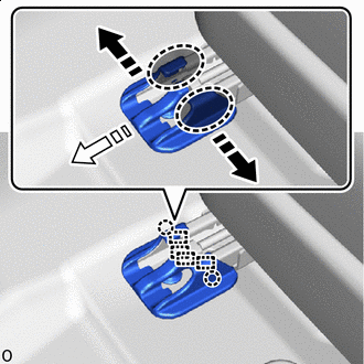
Place Hand Here Remove in this Direction (1) Remove in this Direction (2) Place your hands at the positions shown in the illustration and pull in the removal direction (1) to detach the claws.
-
Slide in the removal direction (2) to detach the guides and remove the front inner seat track bracket cover LH.
-
-
REMOVE FRONT SEAT ASSEMBLY LH
-
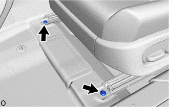
Using a T50 "TORX" socket wrench, remove the 2 "TORX" screws.
-
Operate the slide and vertical power seat switch knob to slide the front seat assembly LH to the frontmost position.
-
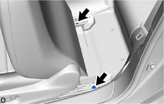
Using a T50 "TORX" socket wrench, remove the 2 "TORX" screws.
-
Operate the slide and vertical power seat switch knob to slide the front seat assembly LH to the center position.
-
Operate the reclining power seat switch knob to set the seatback of the front seat assembly LH perpendicular.
-
Operate the slide and vertical power seat switch knob to set the seat cushion lifter and vertical position of the front seat assembly LH to the uppermost position.
-
Disconnect the cable from the negative (-) battery terminal.
CAUTION:
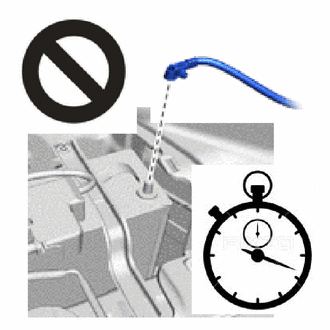
-
Wait at least 90 seconds after disconnecting the cable from the negative (-) battery terminal to disable the SRS system.
-
If an SRS part is accidentally deployed, it may cause a serious injury.
Note
When disconnecting the cable, some systems need to be initialized after the cable is reconnected.
-
-
Tilt the front seat assembly LH backward.
Note
Do not damage the front seat assembly LH or interior parts.
-
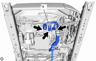
*a Front Seat Airbag Assembly LH Connector Detach the wire harness protector clamps and disconnect the 3 connectors.
-
Disconnect the front seat airbag assembly LH connector.
-
Push the slider to detach the primary lock. Continue pushing and slide the slider to detach the secondary lock and then disconnect the airbag connector.
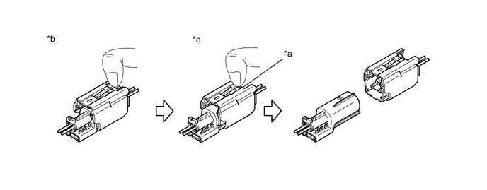
*a Slider *b Push *c Slide - -
-
-
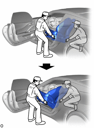
Remove the front seat assembly LH from the vehicle.
Note
-
2 or more people are required when carrying the front seat assembly LH out of the vehicle.
-
Protect the front seat legs.
-
Do not damage the front seat assembly LH, body exterior or interior parts.
-
-