POP UP HOOD SENSOR INSTALLATION

CAUTION / NOTICE / HINT
PROCEDURE
-
INSTALL FRONT BUMPER ENERGY ABSORBER
-
Install the pedestrian detection chamber assembly to the front bumper energy absorber.
Note
-
Securely install the pedestrian detection chamber to the front bumper energy absorber fittings.
-
When connecting the pedestrian detection chamber assembly connector, push it straight in so as not to twist it.
-
Check that the chamber alignment mark is within the anchor range.
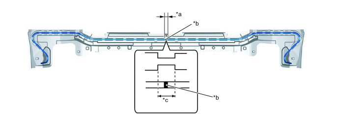
*a 10 mm (0.394 in.) *b Alignment Mark *c Anchor Range - - -
-
Attach the guides to install the front bumper energy absorber to No. 2 front bumper mounting bracket.
Note
When install the pedestrian detection chamber, take care not to damage the front bumper energy absorber.
-
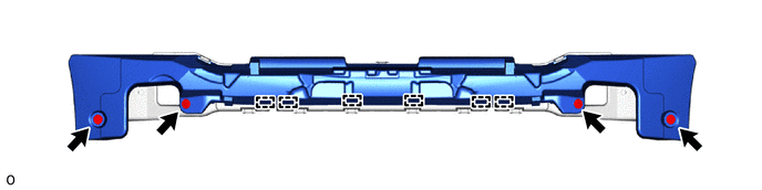
Install the 4 new clips.
-
-
INSTALL PEDESTRIAN DETECTION CHAMBER ASSEMBLY
-
Check that there is no blockage in the breathing filter due to foreign matter.
-
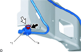
*1 Pedestrian Protection Sensor *a Breathing Filter 
Bolt 
Nut Install the pedestrian detection chamber sensor assembly to the No. 2 front bumper mounting bracket with a new bolt and new nut so that the breathing filter points downward.
- Torque:
- 3.5 N*m { 36 kgf*cm, 31 in.*lbf }
Note
-
Do not reuse the pedestrian detection chamber assembly if subjected to any strong impact (such as dropping) during operation.
-
Do not reuse the tightening bolt or nut of the pedestrian protection sensor.
-
Hold the pedestrian protection sensor so as not to damage the No. 2 front bumper mounting bracket.
-
When connecting the pedestrian detection chamber assembly connector, push it straight in so as not to twist it.
-
When connecting any pedestrian detection chamber connector, take care not to damage the airbag wire harness.
-
Do not open/close or move the tightening clips of the pedestrian detection chamber and pedestrian protection sensor.
Tech Tips
Use the same procedure for the other side.
-
Check that there is no looseness in the installation parts of the pedestrian detection chamber assembly.
-
-
INSTALL NO. 2 FRONT BUMPER MOUNTING BRACKET
-
INSTALL FRONT BUMPER ASSEMBLY
-
CONNECT CABLE TO NEGATIVE BATTERY TERMINAL
Note
When disconnecting the cable, some systems need to be initialized after the cable is reconnected.
-
INSTALL NO. 2 DECK BOARD
-
PERFORM DIAGNOSTIC SYSTEM CHECK
-
CHECK SRS WARNING LIGHT