POP UP HOOD LIFTER(for Front Side) INSTALLATION

CAUTION / NOTICE / HINT
Tech Tips
-
Use the same procedure for RHD and LHD vehicles.
-
The procedure listed below is for LHD vehicles.
PROCEDURE
-
INSTALL POP UP HOOD LIFTER ASSEMBLY LH
-
Check that the engine switch is off.
-
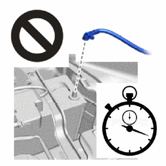
Check that the cable is disconnected from the negative (-) battery terminal.
CAUTION:
-
Wait at least 90 seconds after disconnecting the cable from the negative (-) battery terminal to disable the SRS system.
-
If the airbag deploys for any reason, it may cause a serious accident.
-
-
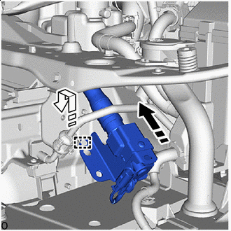

Install in this Direction (1) 
Install in this Direction (2) Move the pop up hood lifter assembly LH in the installation direction (1) and pass it between the wire.
-
Move the pop up hood lifter assembly LH in the installation direction (2) and attach the hook.
-
Install the pop up hood lifter assembly LH with the 3 bolts.
- Torque:
- 9.0 N*m { 92 kgf*cm, 80 in.*lbf }
-
Connect the pop up hood lifter assembly LH connector.
-
Before connecting the connector, check that the position of the housing lock is correct as shown in the illustration.
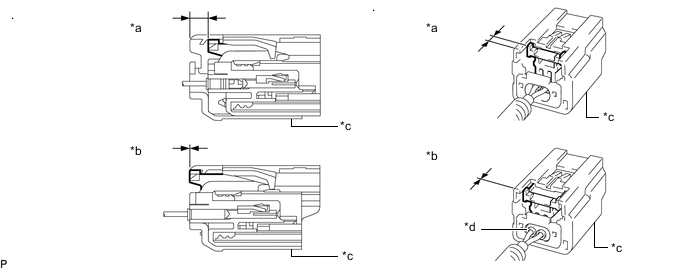
*a Correct *b Incorrect *c CPA *d Housing -
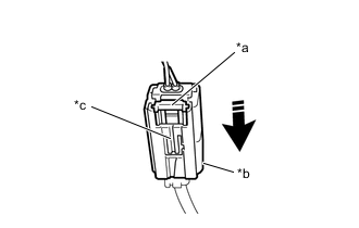
*a Housing Lock *b CPA *c CPA Upper Part Connect in this Direction While holding the CPA be sure to engage the connectors until they are locked and check that the CPA is in its original position (when locking, make sure that a click sound can be heard).
Note
Do not push down the upper part of the CPA shown in the illustration when connecting the pop up hood lifter assembly LH connector.
-
-
-
INSTALL POP UP HOOD LIFTER ASSEMBLY RH
-
Check that the engine switch is off.
-
Check that the cable is disconnected from the negative (-) battery terminal.
CAUTION:
-
Wait at least 90 seconds after disconnecting the cable from the negative (-) battery terminal to disable the SRS system.
-
If the airbag deploys for any reason, it may cause a serious accident.
-
-
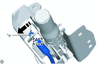
*a End of Hood Lock Control Assembly Install in this Direction Move the end of the hood lock control assembly in the direction of the arrow shown in the illustration and install it to the pop up hood lifter assembly RH.
-
Connect the clamp.
-
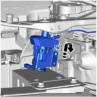
Install in this Direction Move the pop up hood lifter assembly RH in the direction of the arrow shown in the illustration and attach the hook.
-
Install the pop up hood lifter assembly RH with the 3 bolts.
- Torque:
- 9.0 N*m { 92 kgf*cm, 80 in.*lbf }
-
Connect the pop up hood lifter assembly RH connector.
-
Before connecting the connector, check that the position of the housing lock is correct as shown in the illustration.
*a Correct *b Incorrect *c CPA *d Housing -
*a Housing Lock *b CPA *c CPA Upper Part Connect in this Direction While holding the CPA be sure to engage the connectors until they are locked and check that the CPA is in its original position (when locking, make sure that a click sound can be heard).
Note
Do not push down the upper part of the CPA shown in the illustration when connecting the pop up hood lifter assembly RH connector.
-
-
-
INSTALL HOOD LOCK CONTROL ASSEMBLY (for RH Side)
-
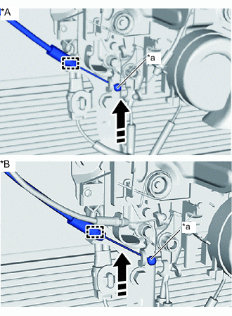
*A for LHD *B for RHD *a End of Hood Lock Control Assembly Install in this Direction Move the end of the hood lock control assembly in the direction of the arrow shown in the illustration and install it to the hood lock assembly.
-
Connect the clamp.
-
-
INSTALL HOOD LOCK CONTROL CABLE COVER RH (for RH Side)
-
INSTALL HOOD LOCK RELEASE LEVER PROTECTOR (for RH Side)
-
INSTALL FRONT AIRBAG SENSOR LH (for LH Side)
-
INSTALL FRONT AIRBAG SENSOR RH (for RH Side)
Tech Tips
Use the same procedure for the LH side.
-
CONNECT CABLE TO NEGATIVE BATTERY TERMINAL
Note
When disconnecting the cable, some systems need to be initialized after the cable is reconnected.
-
INSTALL NO .2 DECK BOARD
-
PERFORM DIAGNOSTIC SYSTEM CHECK
-
CHECK SRS WARNING LIGHT
-
ADJUST HEADLIGHT AIMING