POP UP HOOD ECU REMOVAL
CAUTION / NOTICE / HINT
The necessary procedures (adjustment, calibration, initialization or registration) that must be performed after parts are removed, installed or replaced during the pedestrian detection ECU assembly removal/installation are shown below.
| Replacement Part or Procedure | Necessary Procedures | Effects / Inoperative when not Performed | Link |
|---|---|---|---|
| Disconnect cable from negative (-) battery terminal | Memorize steering angle neutral point | LKA/LDA system | |
| Pre-collision system | |||
| Parking assist monitor system | |||
| Steering sensor zero point calibration | Variable gear ratio steering system |
Tech Tips
-
Use the same procedure for RHD and LHD vehicles.
-
The procedure listed below is for LHD vehicles.
PROCEDURE
-
PRECAUTION
Note
After turning the engine switch off, waiting time may be required before disconnecting the cable from the negative (-) battery terminal. Therefore, make sure to read the disconnecting the cable from the negative (-) battery terminal notices before proceeding with work.
-
REMOVE NO. 2 DECK BOARD
-
DISCONNECT CABLE FROM NEGATIVE BATTERY TERMINAL
CAUTION:
-
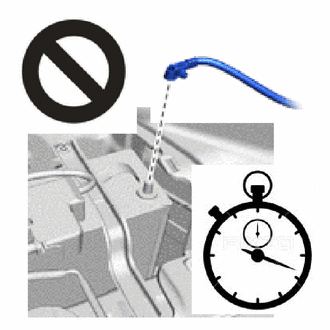
Wait at least 90 seconds after disconnecting the cable from the negative (-) battery terminal to disable the SRS system.
-
If the pop up hood lifter deploys for any reason, it may cause a serious accident.
Note
When disconnecting the cable, some systems need to be initialized after the cable is reconnected.
-
-
REMOVE CONSOLE BOX ASSEMBLY
-
REMOVE NO. 1 CONSOLE BOX SUPPORT
-
REMOVE PEDESTRIAN DETECTION ECU ASSEMBLY
-
Check that the engine switch is off.
-
Check that the cable is disconnected from the negative (-) battery terminal.
CAUTION:
-
Wait at least 90 seconds after disconnecting the cable from the negative (-) battery terminal to disable the SRS system.
-
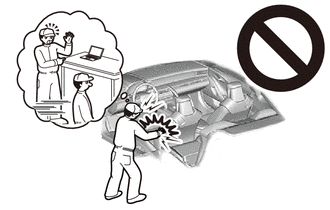
If this procedure is performed without disconnecting the negative (-) battery terminal of the battery, the pop up hood lifter may deploy even if an impact is applied only to the pedestrian detection ECU assembly. Therefore, make sure that the negative (-) battery terminal of the battery is disconnected before performing this procedure.
-
-
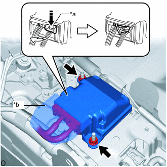
*a Lock Lever *b Water Resistant Sheet 
Push 
Release in this Direction Push the lock lever in the direction shown in the illustration to release the lock and disconnect the connector.
Note
Do not remove the water resistant sheet.
-
Remove the 2 nuts and pedestrian detection ECU assembly.
Note
-
Do not subject the pedestrian detection ECU assembly to any strong impact (such as dropping).
-
If the pedestrian detection ECU assembly is subjected to any strong impact, replace the pedestrian detection ECU assembly with a new one.
-
-