HEADUP DISPLAY SYSTEM Main Switch Circuit
DESCRIPTION
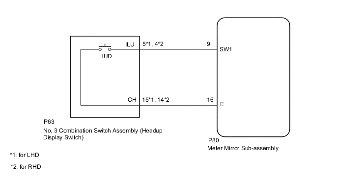
The no. 3 combination switch assembly (headup display switch) and meter mirror sub-assembly are connected via direct line. The meter mirror sub-assembly can be turned off and on by operating the no. 3 combination switch assembly (headup display switch).
WIRING DIAGRAM
PROCEDURE
-
READ VALUE USING GTS (MAIN SWITCH)
-
Connect the GTS to the DLC3.
-
Turn the engine switch on (IG).
-
Turn the GTS on.
-
Enter the following menus: Body Electrical / Head Up Display / Data List.
-
Read the Data List according to the display on the GTS.
Body Electrical > Head Up Display > Data ListTester Display Measurement Item Range Normal Condition Diagnostic Note Main Switch No. 3 combination switch assembly (headup display switch) status OFF or ON OFF: Switch released
ON: Switch pushed
-
Body Electrical > Head Up Display > Data ListTester Display Main Switch OK No. 3 combination switch assembly (headup display switch) condition displayed on the GTS changes with the actual switch operation. Result Proceed to OK NG
OK 
REPLACE METER MIRROR SUB-ASSEMBLY Click here
NG 
-
-
INSPECT NO. 3 COMBINATION SWITCH ASSEMBLY (HEADUP DISPLAY SWITCH)
-
Remove the No. 3 combination switch assembly (headup display switch).
-
Inspect the No. 3 combination switch assembly (headup display switch).
Result Proceed to OK NG
NG
REPLACE NO. 3 COMBINATION SWITCH ASSEMBLY (HEADUP DISPLAY SWITCH) Click here
OK
-
-
CHECK HARNESS AND CONNECTOR (METER MIRROR SUB-ASSEMBLY - NO. 3 COMBINATION SWITCH ASSEMBLY [HEADUP DISPLAY SWITCH])
-
Disconnect the P80 meter mirror sub-assembly connector.
-
Disconnect the P63 No. 3 combination switch assembly (headup display switch) connector.
-
Measure the resistance according to the value(s) in the table below.
-
for LHD:
Standard Resistance Tester Connection Condition Specified Condition P80-9 (SW1) - P63-5 (ILU) Always Below 1 Ω P80-16 (E) - P63-15 (CH) Always Below 1 Ω P80-9 (SW1) or P63-5 (ILU) - Body ground Always 10 kΩ or higher P80-16 (E) or P63-15 (CH) - Body ground Always 10 kΩ or higher -
for RHD:
Standard Resistance Tester Connection Condition Specified Condition P80-9 (SW1) - P63-4 (ILU) Always Below 1 Ω P80-16 (E) - P63-114 (CH) Always Below 1 Ω P80-9 (SW1) or P63-4 (ILU) - Body ground Always 10 kΩ or higher P80-16 (E) or P63-14 (CH) - Body ground Always 10 kΩ or higher
Result Proceed to OK NG -
OK
REPLACE METER MIRROR SUB-ASSEMBLY Click here
NG
REPAIR OR REPLACE HARNESS OR CONNECTOR
-