TELEMATICS SYSTEM, Diagnostic DTC:B15C5
| DTC Code | DTC Name |
|---|---|
| B15C5 | Emergency Switch Error (Open or Short) |
DESCRIPTION
This DTC is stored when the telephone transceiver assembly detects an open or short circuit in the manual (SOS) switch.
| DTC No. | Detection Item | DTC Detection Condition | Trouble Area |
|---|---|---|---|
| B15C5 | Emergency Switch Error (Open or Short) | Open or short circuit in the manual (SOS) switch is detected. |
|
WIRING DIAGRAM
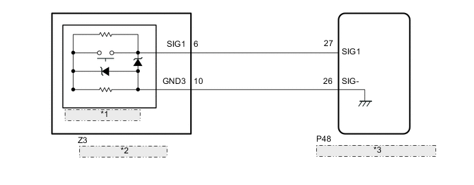
| *1 | Manual (SOS) Switch |
| *2 | Map Light Sub-assembly |
| *3 | Telephone Transceiver Assembly |
CAUTION / NOTICE / HINT
Note
-
Depending on the parts that are replaced during vehicle inspection or maintenance, performing initialization, registration or calibration may be needed. Refer to Registration for Telematics System.
-
When replacing the telephone transceiver assembly, make sure to replace it with a new one.
PROCEDURE
-
CHECK FOR DTC
-
Turn the engine switch off.
-
Connect the GTS to the DLC3.
-
Turn the engine switch on (IG) and wait for 20 seconds.
-
Turn the GTS on.
-
Check for DTCs and check that no DTCs are output.
Body Electrical > Telematics > Trouble CodesOK No DTCs are output. Result Proceed to OK NG
OK 
USE SIMULATION METHOD TO CHECK Click here
NG 
-
-
CHECK MAP LIGHT SUB-ASSEMBLY (MANUAL (SOS) SWITCH)
-
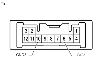
*a Component without harness connected
(Map Light Sub-assembly [Manual (SOS) Switch])
Remove the map light sub-assembly (manual (SOS) switch).
-
Measure the resistance according to the value(s) in the table below.
Standard Resistance Tester Connection Switch Condition Specified Condition 6 (SIG1) - 10 (GND3) Manual (SOS) switch not pressed 392 to 432 Ω 6 (SIG1) - 10 (GND3) Manual (SOS) switch pressed 78 to 86 Ω Result Proceed to OK NG
NG
REPLACE MAP LIGHT SUB-ASSEMBLY (MANUAL (SOS) SWITCH) Click here
OK
-
-
CHECK HARNESS AND CONNECTOR (TELEPHONE TRANSCEIVER ASSEMBLY - MAP LIGHT SUB-ASSEMBLY [MANUAL (SOS) SWITCH])
-
Disconnect the P48 telephone transceiver assembly connector.
-
Disconnect the Z3 map light sub-assembly (manual (SOS) switch) connector.
-
Measure the resistance according to the value(s) in the table below.
Standard Resistance Tester Connection Condition Specified Condition P48-27 (SIG1) - Z3-6 (SIG1) Always Below 1 Ω P48-26 (SIG-) - Z3-10 (GND3) Always Below 1 Ω P48-27 (SIG1) or Z3-6 (SIG1) - Body ground Always 10 kΩ or higher P48-26 (SIG-) or Z3-10 (GND3) - Body ground Always 10 kΩ or higher Result Proceed to OK NG
NG
REPAIR OR REPLACE HARNESS OR CONNECTOR
OK
-
-
REPLACE TELEPHONE TRANSCEIVER ASSEMBLY
-
Replace the telephone transceiver assembly with a new one.
Result Proceed to NEXT
NEXT
PERFORM REGISTRATION Click here
-