ACTIVE NOISE CONTROL SYSTEM Input / Output Signal Circuit
DESCRIPTION
The stereo component equalizer assembly uses this circuit to send and receive signals to and from the stereo component assembly.
WIRING DIAGRAM
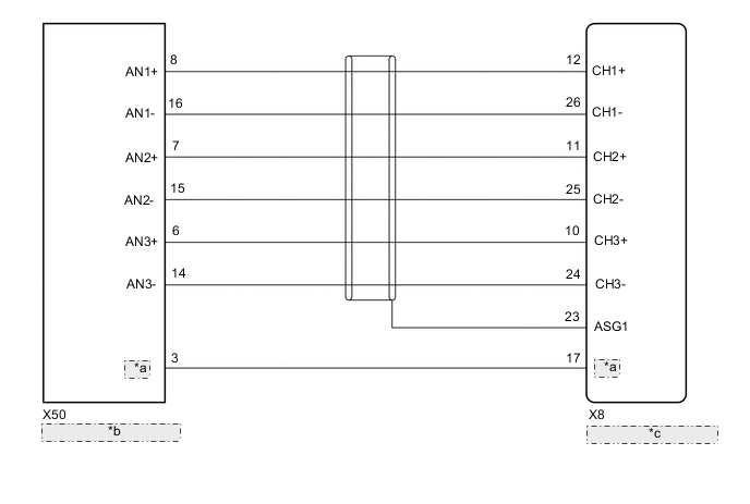
| *a | ACNT |
| *b | Stereo Component Amplifier Assembly |
| *c | Stereo Component Equalizer Assembly |
PROCEDURE
-
CHECK HARNESS AND CONNECTOR (STEREO COMPONENT EQUALIZER ASSEMBLY - STEREO COMPONENT AMPLIFIER ASSEMBLY)
-
Disconnect the X8 stereo component equalizer assembly connector.
-
Disconnect the X50 stereo component amplifier assembly connector.
-
Measure the resistance according to the value(s) in the table below.
Standard Resistance Tester Connection Condition Specified Condition X8-12 (CH1+) - X50-8 (AN1+) Always Below 1 Ω X8-26 (CH1-) - X50-16 (AN1-) Always Below 1 Ω X8-11 (CH2+) - X50-7 (AN2+) Always Below 1 Ω X8-25 (CH2-) - X50-15 (AN2-) Always Below 1 Ω X8-10 (CH3+) - X50-6 (AN3+) Always Below 1 Ω X8-24 (CH3-) - X50-14 (AN3-) Always Below 1 Ω X8-23 (ASG1) - Body ground Always Below 1 Ω X8-17 (ACNT) - X50-3 (ACNT) Always Below 1 Ω X8-12 (CH1+) - Body ground Always 10 kΩ or higher X8-26 (CH1-) - Body ground Always 10 kΩ or higher X8-11 (CH2+) - Body ground Always 10 kΩ or higher X8-25 (CH2-) - Body ground Always 10 kΩ or higher X8-10 (CH3+) - Body ground Always 10 kΩ or higher X8-24 (CH3-) - Body ground Always 10 kΩ or higher X8-17 (ACNT) - Body ground Always 10 kΩ or higher Result Proceed to OK NG
OK 
PROCEED TO NEXT SUSPECTED AREA SHOWN IN PROBLEM SYMPTOMS TABLE Click here
NG
REPAIR OR REPLACE HARNESS OR CONNECTOR
-