ACTIVE NOISE CONTROL SYSTEM, Diagnostic DTC:P033531
| DTC Code | DTC Name |
|---|---|
| P033531 | Crankshaft Position Sensor "A" No Signal |
DESCRIPTION
This DTC is output when a malfunction has occurred in the engine pulse signal system from the ECM.
| DTC No. | Detection Item | DTC Detection Condition | Trouble Area |
|---|---|---|---|
| P033531 | Crankshaft Position Sensor "A" No Signal | Engine running, engine speed is 500 rpm or higher and below 6000 rpm 3 seconds after the engine switch is turned on (ACC), the stereo component equalizer assembly detects a malfunction in the engine pulse signal system for 10 seconds or more continuously* |
|
Tech Tips
*: Malfunction monitoring is not performed during the following conditions to prevent erroneous detection.
-
The battery voltage is less than 9.5 V.
-
Before 3 seconds have elapsed after battery voltage has returned to normal.
WIRING DIAGRAM
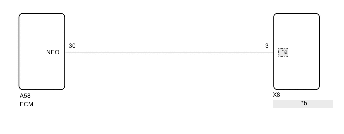
| *a | NEI |
| *b | Stereo Component Equalizer Assembly |
CAUTION / NOTICE / HINT
Note
Refer to Click here when replacing the ECM.
PROCEDURE
-
CLEAR DTC
-
Clear the DTCs.
Body Electrical > Active Noise Control > Clear DTCsResult Proceed to NEXT
NEXT 
-
-
CHECK FOR DTC
-
Check for DTCs.
Body Electrical > Active Noise Control > Trouble CodesOK DTC P033531 is not output. Result Proceed to OK NG
OK 
USE SIMULATION METHOD TO CHECK Click here
NG
-
-
CHECK HARNESS AND CONNECTOR (STEREO COMPONENT EQUALIZER ASSEMBLY - ECM)
-
Disconnect the X8 stereo component equalizer assembly connector.
-
Disconnect the A58 ECM connector.
-
Measure the resistance according to the value(s) in the table below.
Standard Resistance Tester Connection Condition Specified Condition X8-3 (NEI) - A58-30 (NEO) Always Below 1 Ω X8-3 (NEI) - Body ground Always 10 kΩ or higher Result Proceed to OK NG
NG
REPAIR OR REPLACE HARNESS OR CONNECTOR
OK
-
-
CHECK ECM
-
According to the table and using an oscilloscope, measure the waveform with the stereo component equalizer assembly connected.
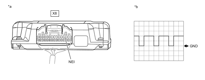
*a Component with harness connected
(Stereo Component Equalizer Assembly)
*b Waveform Item Condition Measurement terminal X8-3 (NEI) - Body ground Tool setting 5 V/DIV., 20 ms./DIV. Vehicle condition Idling with warm engine OK The waveform is similar to that shown in the illustration. Tech Tips
The oscilloscope waveform shown in the illustration is an example for reference only. The waveform fluctuates according to engine speed.
Result Proceed to OK NG
OK
REPLACE STEREO COMPONENT EQUALIZER ASSEMBLY Click here
NG
GO TO SFI SYSTEM w/ Canister Pump Module: GO TO SFI SYSTEM Click here
GO TO SFI SYSTEM w/o Canister Pump Module: GO TO SFI SYSTEM Click here -