STEERING LINKAGE INSPECTION

PROCEDURE
-
INSPECT TIE ROD ASSEMBLY LH
-
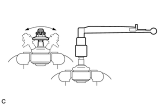
Secure the tie rod assembly LH in a vise between aluminum plates.
Note
Do not overtighten the vise.
-
Install the nut to the stud bolt.
-
Flip the ball joint back and forth 5 times.
-
Using a torque wrench and the nut, turn the stud bolt continuously at a rate of 3 to 5 seconds per turn, and check the turning torque on the 5th turn.
Standard Turning Torque 0.49 to 3.43 N*m (5 to 35 kgf*cm, 5 to 30 in.*lbf) If the turning torque is not within the specified range, replace the tie rod assembly LH with a new one.
-
Check that the ball joint dust cover is not cracked and that there is no grease on it.
If the ball joint dust cover is cracked or there is grease on it, replace the tie rod assembly LH with a new one.
-
-
INSPECT TIE ROD ASSEMBLY RH
Tech Tips
Perform the same procedure as for the LH side.
-
INSPECT TOTAL PRELOAD
Note
Inspect the total preload in a no-load condition by removing the tie rod assembly RH, tie rod assembly LH and steering rack boots.
-
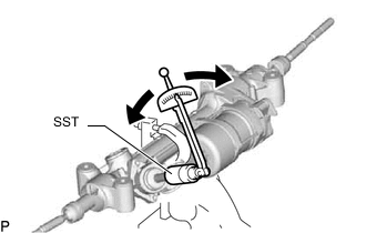
Install SST to the pinion shaft and turn it left and right 5 times or more.
- SST
- 09616-00011
-
Using SST and a torque wrench, turn the pinion shaft continuously at a rate of 4 to 6 seconds per turn to check the total preload of the rack and pinion power steering gear assembly.
Standard Preload 3.05 to 3.95 N*m (32 to 40 kgf*cm, 27 to 34 in.*lbf) Note
-
Check the total preload around the steering rack center position.
-
Do not touch the rack bar while performing the check.
If the total preload is not within the specified range, replace the rack and pinion power steering gear assembly with a new one.
-
-