TILT AND TELESCOPIC MANUAL SWITCH REMOVAL
CAUTION / NOTICE / HINT
The necessary procedures (adjustment, calibration, initialization, or registration) that must be performed after parts are removed, installed, or replaced during the tilt and telescopic manual switch removal/installation are shown below.
| Replacement Part or Procedure | Necessary Procedure | Effect/Inoperative when not Performed | Link |
|---|---|---|---|
| Disconnect cable from negative battery terminal | Memorize steering angle neutral point | LKA/LDA system | |
| Pre-collision system | |||
| Parking assist monitor system | |||
| Steering sensor zero point calibration | Variable gear ratio steering system |
Tech Tips
-
Use the same procedure for RHD and LHD vehicles.
-
The procedure listed below is for LHD vehicles.
PROCEDURE
-
PRECAUTION
Note
After turning the engine switch off, waiting time may be required before disconnecting the cable from the negative (-) battery terminal. Therefore, make sure to read the disconnecting the cable from the negative (-) battery terminal notices before proceeding with work.
-
CUSTOMIZE POWER TILT AND POWER TELESCOPIC STEERING COLUMN SYSTEM
-
Disable the auto tilt away function by changing the customize settings.
Note
Record the current customize setting (whether the auto tilt away function is enabled or disabled) in order to restore the current setting after finishing the operation.
Tech Tips
Performing the above operation causes the auto tilt away function to be disabled when the engine switch is turned off.
-
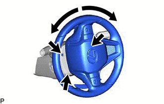
Turn the engine switch on (IG). Operate the tilt and telescopic switch to fully extend and lower the steering column assembly.
-
-
REMOVE NO. 2 DECK BOARD
-
DISCONNECT CABLE FROM NEGATIVE BATTERY TERMINAL
Note
When disconnecting the cable, some systems need to be initialized after the cable is reconnected.
-
REMOVE LOWER STEERING COLUMN COVER SUB-ASSEMBLY
-
Remove the 3 screws.
-
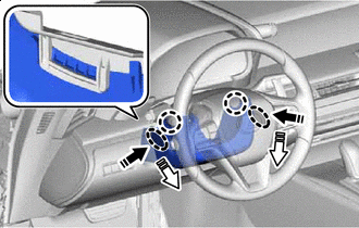

Push Area 
Remove in this Direction (1) 
Remove in this Direction (2) Press in, in the direction shown by the arrow (1) in the illustration, and disengage the claws.
-
Pull out in the direction indicated by the arrow (2) in the illustration, disengage the claws to remove the lower steering column cover.
-
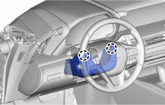
Disengage the 2 claws.
-
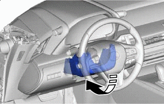

Remove in this Direction Pull in the direction indicated by the arrow to remove the lower steering column cover sub-assembly.
Note
Do not damage the tilt and telescopic switch.
-
-
REMOVE TILT AND TELESCOPIC SWITCH
-
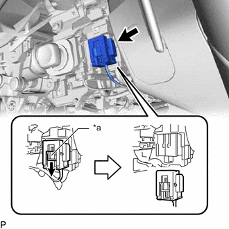
*a Slider Slide the slider to release the lock, and then disconnect the yellow airbag connector from the spiral cable with sensor sub-assembly.
Note
When disconnecting any airbag connector, take care not to damage the airbag wire harness.
-
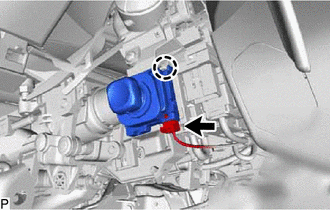
Disconnect the tilt and telescopic connector from the tilt and telescopic switch.
-
Disengage the claw and pull out the tilt and telescopic switch.
-