DYNAMIC REAR STEERING ACTUATOR INSTALLATION

PROCEDURE
-
INSTALL REAR STEERING LINK ASSEMBLY
-
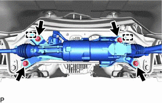
Align the 2 guide pins with the rear suspension member sub-assembly and install the rear steering link assembly with the 4 bolts.
- Torque:
- 97 N*m { 989 kgf*cm, 72 ft.*lbf }
-
Engage the 2 wire harness clamps and install the grommet.
-
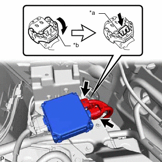
*a Lock of the Lock Lever *b Lock Lever Connect the 2 connectors to the rear steering control ECU.
Tech Tips
When connecting the connector with lock lever, return the lock lever to its original position and securely push in the lock of the lock lever as shown in the illustration.
-
-
INSTALL EXHAUST TAILPIPE ASSEMBLY
-
CONNECT REAR STEERING TIE ROD ASSEMBLY LH
-
Install the rear steering tie rod assembly LH to the rear axle carrier sub-assembly with a new nut.
- Torque:
- 118 N*m { 1203 kgf*cm, 87 ft.*lbf }
-
Connect the skid control sensor wire LH to the rear steering tie rod assembly LH with the bolt.
- Torque:
- 8.5 N*m { 87 kgf*cm, 75 in.*lbf }
-
-
CONNECT REAR STEERING TIE ROD ASSEMBLY RH
Tech Tips
Perform the same procedure as for the LH side.
-
INSTALL REAR WHEELS
-
INSTALL SIDE TRIM BOX
-
INSTALL LUGGAGE COMPARTMENT TRIM COVER RH
-
INSTALL NO. 1 DECK BOARD
-
CONNECT CABLE TO NEGATIVE BATTERY TERMINAL
Note
When disconnecting the cable, some systems need to be initialized after the cable is reconnected.
-
INSTALL NO. 2 DECK BOARD
-
INSPECT AND ADJUST REAR WHEEL ALIGNMENT
-
PERFORM DYNAMIC REAR STEERING SYSTEM CALIBRATION