DYNAMIC REAR STEERING SYSTEM, Diagnostic DTC:C1B26/36, C1B2A/38
| DTC Code | DTC Name |
|---|---|
| C1B26/36 | Motor Power Supply Voltage Circuit(ECU Start-up) |
| C1B2A/38 | Motor Power Supply Voltage Circuit |
DESCRIPTION
When the DRS ECU (rear steering control ECU) detects a problem with the PIG power source circuit, DTC C1B26/36 and C1B2A/38 are stored.
| DTC No. | Detection Item | DTC Detection Condition | Trouble Area | Warning Indicate | Return-to-normal Condition |
|---|---|---|---|---|---|
| C1B26/36 | Motor Power Supply Voltage Circuit(ECU Start-up) | All conditions are met:
|
|
Comes on | Engine switch on (IG) again |
| C1B2A/38 | Motor Power Supply Voltage Circuit | All conditions are met:
|
|
Comes on | Engine switch on (IG) again |
WIRING DIAGRAM
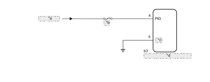
| *a | from Battery |
| *b | ARS |
| *c | GNDY |
| *d | DRS ECU (Rear Steering Control ECU) |
CAUTION / NOTICE / HINT
Note
-
When replacing the DRS ECU (rear steering control ECU), perform neutral position memorization and motor rotation angle sensor calibration.
-
Since DTC C15C9/76 is stored in the VGRS ECU (front steering control ECU), after performing repairs on the dynamic rear steering system, clear the DTCs for the VGRS system.
-
Before performing troubleshooting, turn off the remote service function.
-
Inspect the fuses for circuits related to this system before performing the following inspection procedure.
PROCEDURE
-
READ VALUE USING GTS (PIG POWER SUPPLY VOLTAGE)
-
Turn the engine switch off.
-
Connect the GTS to the DLC3.
-
Turn the engine switch on (IG).
-
Turn the GTS on.
-
Enter the following menus: Chassis / DRS / Data List.
Chassis > DRS > Data ListTester Display Measurement Item Range Normal Condition Diagnostic Note PIG Power Supply Voltage PIG power supply voltage Min.: 0.00 V
Max.: 255.99 V
11 to 14 V -
Chassis > DRS > Data ListTester Display PIG Power Supply Voltage OK 11 to 14 V Result Proceed to OK NG
OK 
USE SIMULATION METHOD TO CHECK Click here
NG 
-
-
INSPECT DRS ECU (REAR STEERING CONTROL ECU) (PIG, GNDY TERMINAL)
-
Turn the engine switch off.
-
Check the connection condition of the DRS ECU (rear steering control ECU) connector.
-
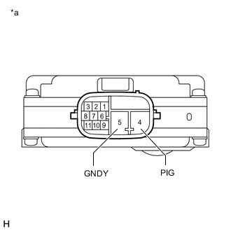
*a Component without harness connected
(DRS ECU [Rear Steering Control ECU])
Disconnect the b3 DRS ECU (rear steering control ECU) connector.
-
Measure the resistance according to the value(s) in the table below.
Standard Resistance Tester Connection Condition Specified Condition 4 (PIG) - 5 (GNDY) Always 100 kΩ or higher Result Proceed to OK NG
NG
REPLACE DRS ECU (REAR STEERING CONTROL ECU) Click here
OK
-
-
CHECK HARNESS AND CONNECTOR (PIG CIRCUIT)
-
Turn the engine switch off.
-
Disconnect the b3 DRS ECU (rear steering control ECU) connector.
-
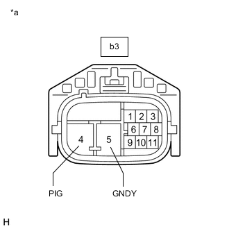
*a Front view of wire harness connector
(to DRS ECU [Rear Steering Control ECU])
Measure the voltage according to the value(s) in the table below.
Standard Voltage: Tester Connection Condition Specified Condition b3-4 (PIG) - b3-5 (GNDY) Always 11 to 14 V Result Proceed to OK NG
OK
REPLACE DRS ECU (REAR STEERING CONTROL ECU) Click here
NG
REPAIR OR REPLACE HARNESS OR CONNECTOR
-