POWER STEERING SYSTEM, Diagnostic DTC:C1551
| DTC Code | DTC Name |
|---|---|
| C1551 | IG Power Supply Voltage |
DESCRIPTION
When a problem occurs in the power source circuit, the fail-safe function works to stop the power assist.
| DTC No. | Detection Item | DTC Detection Condition | Trouble Area | Warning Indicate | Return-to-normal Condition | Note |
|---|---|---|---|---|---|---|
| C1551 | IG Power Supply Voltage | When the PIG power supply voltage is normal and the IG power supply voltage is 18.5 V or higher |
|
EPS warning light: Comes on | The ECU judges the system has returned to normal | - |
WIRING DIAGRAM
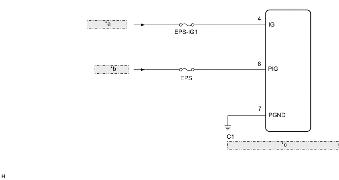
| *a | from IG1 Relay |
| *b | from Battery |
| *c | Power Steering ECU (Rack and Pinion Power Steering Gear Assembly) |
CAUTION / NOTICE / HINT
Note
-
If the rack and pinion power steering gear assembly has been replaced, perform assist map writing and torque sensor zero point calibration.
PROCEDURE
-
CHECK HARNESS AND CONNECTOR (BATTERY - RACK AND PINION POWER STEERING GEAR ASSEMBLY)
-
Disconnect the C1 rack and pinion power steering gear assembly connector.

*a Front view of wire harness connector
(to Rack and Pinion Power Steering Gear Assembly)
- - -
Measure the voltage according to the value(s) in the table below.
Standard Voltage Tester Connection Condition Specified Condition C1-4 (IG) - Body ground Engine switch on (IG) Below 18.5 V Result Proceed to OK NG
NG 
REPAIR OR REPLACE HARNESS OR CONNECTOR
OK 
-
-
CHECK FOR DTC
-
Clear the DTCs.
Chassis > EMPS > Clear DTCs -
Check for DTCs.
Chassis > EMPS > Trouble CodesResult Result Proceed to DTC is output. A DTC is not output. B
A
REPLACE RACK AND PINION POWER STEERING GEAR ASSEMBLY Click here
B
USE SIMULATION METHOD TO CHECK Click here
-