ELECTRIC PARKING BRAKE SYSTEM, Diagnostic DTC:C13A1/12
| DTC Code | DTC Name |
|---|---|
| C13A1/12 | Short in Power Supply Relay Circuit |
DESCRIPTION
C13A1/12 is stored if the power supply relay in the parking brake ECU assembly has a short circuit.
C13A1/12 is stored if the engine switch is off and a voltage of 2.5 V or higher is applied to the IG terminal and an electric parking brake switch assembly malfunction or wire harness malfunction between the switch and ECU occurs.
| DTC No. | Detection Item | DTC Detection Condition | Trouble Area | Memory | Note |
|---|---|---|---|---|---|
| C13A1/12 | Short in Power Supply Relay Circuit | Both of following conditions are met:
|
|
Yes | An electric parking brake system malfunction is displayed on the multi-information display. |
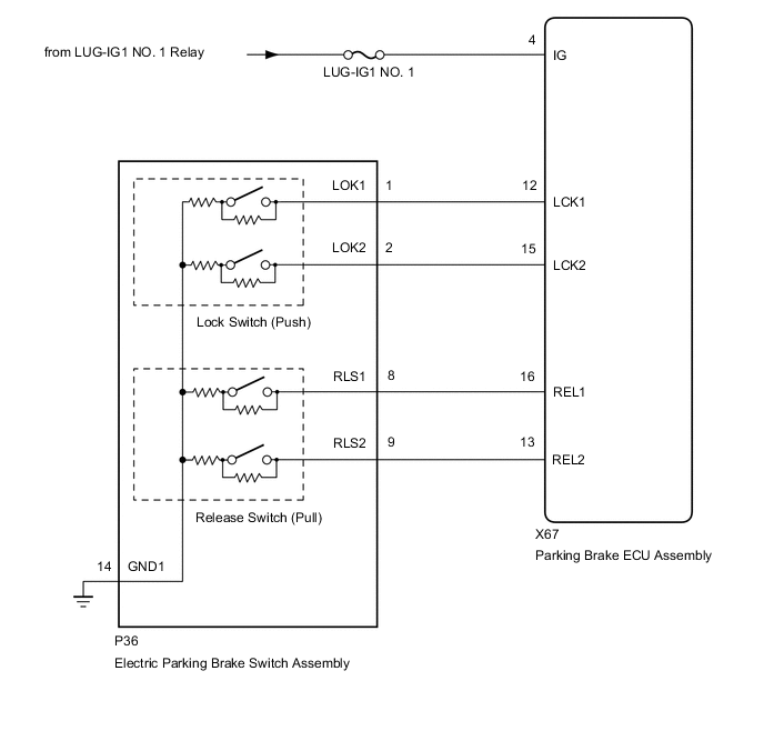
WIRING DIAGRAM
CAUTION / NOTICE / HINT
Note
-
Inspect the fuses for circuits related to this system before performing the following inspection procedure.
-
The electric parking brake may still operate up to 20 seconds after the engine switch is turned off. Before disconnecting connectors or fuses, turn the engine switch off and wait 20 seconds or more.
-
If the parking brake ECU assembly is replaced, perform the "Reset Memory" and "Acquire Tension Sensor Zero Point" procedures
PROCEDURE
-
CHECK HARNESS AND CONNECTOR (PARKING BRAKE ECU ASSEMBLY - IG POWER SOURCE CIRCUIT)
-
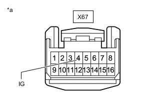
*a Front view of wire harness connector
(to Parking Brake ECU Assembly)
Turn the engine switch off.
-
Disconnect the parking brake ECU assembly connector.
-
Measure the voltage according to the value(s) in the table below.
Standard Voltage Tester Connection Switch Condition Specified Condition X67-4 (IG) - Body ground Engine switch off Below 2.5 V Result Proceed to OK NG
NG 
REPAIR IG POWER SOURCE CIRCUIT
OK 
-
-
INSPECT ELECTRIC PARKING BRAKE SWITCH ASSEMBLY
-
Inspect the electric parking brake switch assembly.
Result Proceed to OK NG
NG
REPLACE ELECTRIC PARKING BRAKE SWITCH ASSEMBLY Click here
OK
-
-
CHECK HARNESS AND CONNECTOR (PARKING BRAKE ECU ASSEMBLY - ELECTRIC PARKING BRAKE SWITCH ASSEMBLY)
-
Turn the engine switch off.
-
Disconnect the P36 electric parking brake switch assembly connector.
-
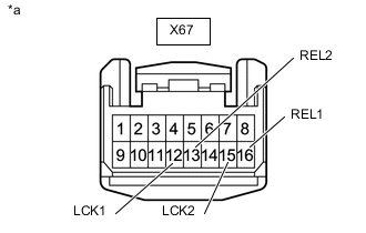
*a Front view of wire harness connector
(to Parking Brake ECU Assembly)
Disconnect the parking brake ECU assembly connector.
-
Measure the resistance according to the value(s) in the table below.
Standard Resistance Tester Connection Condition Specified Condition X67-12 (LCK1) - Body ground Always 10 kΩ or higher X67-13 (REL2) - Body ground Always 10 kΩ or higher X67-15 (LCK2) - Body ground Always 10 kΩ or higher X67-16 (REL1) - Body ground Always 10 kΩ or higher Result Proceed to OK NG
OK
REPLACE PARKING BRAKE ECU ASSEMBLY Click here
NG
REPAIR OR REPLACE HARNESS OR CONNECTOR
-