ELECTRIC PARKING BRAKE SYSTEM, Diagnostic DTC:C13AD/23
| DTC Code | DTC Name |
|---|---|
| C13AD/23 | Open in +B Circuit |
DESCRIPTION
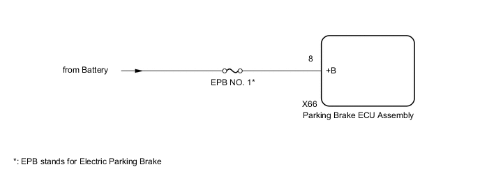
The parking brake ECU assembly is supplied with power to operate the motor via the +B terminals.
| DTC No. | Detection Item | DTC Detection Condition | Trouble Area | Memory | Note |
|---|---|---|---|---|---|
| C13AD/23 | Open in +B Circuit | All of following conditions are met:
Tech Tips *: This value is based on the assumption that the battery voltage is 11 V. The threshold changes according to the battery voltage. For details, refer to "Threshold Changes According to Battery Voltage". |
|
Yes | An electric parking brake system malfunction is displayed on the multi-information display. |
Figure 1. Threshold Changes According to Battery Voltage
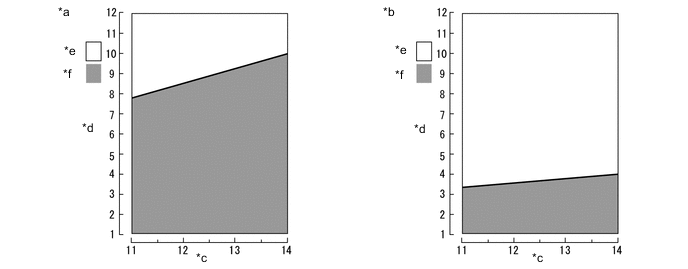
| *a | Parking Brake Motor Not Operating | *b | Parking Brake Motor Operating |
| *c | Battery Voltage (V) | *d | +B Terminal Voltage (V) |
| *e | Normal Range | *f | DTC Detection Range |
WIRING DIAGRAM
CAUTION / NOTICE / HINT
Note
-
Inspect the fuses for circuits related to this system before performing the following inspection procedure.
-
The electric parking brake may still operate up to 20 seconds after the engine switch is turned off. Before disconnecting connectors or fuses, turn the engine switch off and wait 20 seconds or more.
-
If the parking brake ECU assembly is replaced, perform the "Reset Memory" and "Acquire Tension Sensor Zero Point" procedures.
PROCEDURE
-
READ VALUE USING GTS (+B VOLTAGE VALUE)
-
Turn the engine switch off.
-
Connect the GTS to the DLC3.
-
Turn the engine switch on (IG) and the GTS on.
-
Enter the following menus: Chassis / Electric Parking Brake / Data List.
-
Check the values by referring to the table below.
Chassis > Electric Parking Brake > Data ListTester Display Measurement Item Range Normal Condition Diagnostic Note +B Voltage Value Electric parking brake motor power source information display Lo, Mid or Hi Hi -
Chassis > Electric Parking Brake > Data ListTester Display +B Voltage Value OK Values are as shown in normal condition. Result Proceed to OK NG
OK 
USE SIMULATION METHOD TO CHECK Click here
NG 
-
-
CHECK HARNESS AND CONNECTOR (PARKING BRAKE ECU ASSEMBLY - BATTERY)
-
Turn the engine switch off.
-
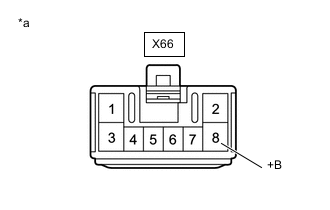
*a Front view of wire harness connector
(to Parking Brake ECU Assembly)
Disconnect the parking brake ECU assembly connector.
-
Measure the voltage according to the value(s) in the table below.
Standard Voltage Tester Connection Switch Condition Specified Condition X66-8 (+B)- Body ground Engine switch off 11 to 14 V Result Proceed to OK NG
OK
REPLACE PARKING BRAKE ECU ASSEMBLY Click here
NG
REPAIR OR REPLACE HARNESS OR CONNECTOR
-