BRAKE MASTER CYLINDER(for RHD) DISASSEMBLY
PROCEDURE
-
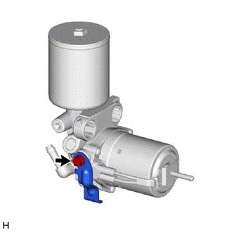
REMOVE RESERVOIR BRACKET
-
Disconnect the connector.
-
Detach the connector clamp.
-
Detach the 2 claws and disconnect the wire harness.
-
Remove the bolt and reservoir bracket from the brake master with stroke simulator cylinder assembly.
-
-
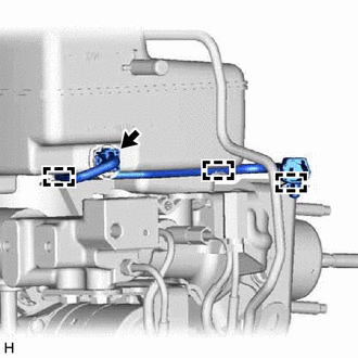
REMOVE NO. 2 BRAKE ACTUATOR TUBE
-
Using a union nut wrench, disconnect the No. 2 brake actuator tube.
-
Remove the bolt and No. 2 brake actuator tube.
Note
-
Do not kink or damage the No. 2 brake actuator tube.
-
Do not allow any foreign matter such as dirt or dust to enter the No. 2 brake actuator tube from the connecting parts.
-
-
-
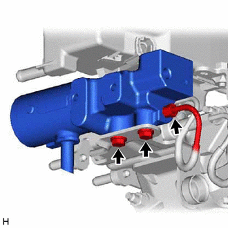
REMOVE BRAKE BOOSTER WITH ACCUMULATOR PUMP ASSEMBLY
-
Detach the clip from the master cylinder bracket.
-
Remove the bolt and brake actuator case from the master cylinder bracket.
-
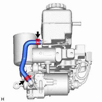
Slide the clip and disconnect the reservoir hose from the brake master cylinder reservoir assembly and brake booster with accumulator pump assembly.
-
Remove the nut and brake booster with accumulator pump assembly from the brake master with stroke simulator cylinder assembly.
-
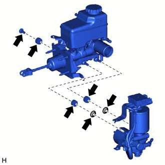
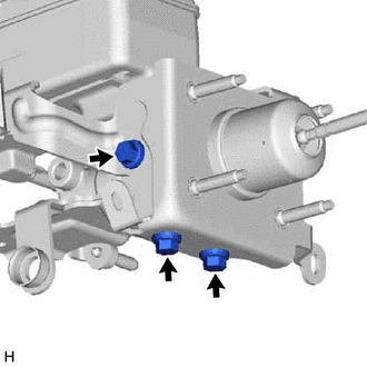
Remove the 2 brake booster pump bushes and 2 brake booster pump collars from the brake booster with accumulator pump assembly.
-
Remove the brake booster pump bush and brake booster pump collar from the brake stroke simulator bracket.
-
-
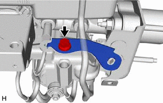
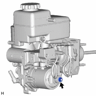
REMOVE TUBE CLAMP BRACKET
-
Remove the bolt and tube clamp bracket from the brake booster with accumulator pump assembly.
-
-
REMOVE NO. 1 BRAKE ACTUATOR BRACKET
-
Remove the bolt and No. 1 brake actuator bracket from the brake booster with accumulator pump assembly.
-
-
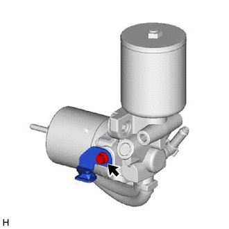
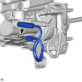
REMOVE BRAKE STROKE SIMULATOR CYLINDER SUB-ASSEMBLY
-
Using a union nut wrench, disconnect the brake master cylinder tube from the brake stroke simulator cylinder sub-assembly.
Note
-
Do not kink or damage the brake master cylinder tube.
-
Do not allow any foreign matter such as dirt or dust to enter the brake master cylinder tube from the connecting parts.
-
-
Remove the 2 bolts and brake stroke simulator cylinder sub-assembly from the brake stroke simulator bracket.
-
-
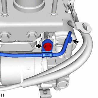
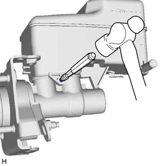
REMOVE BRAKE MASTER CYLINDER TUBE
-
Using a union nut wrench, disconnect the brake master cylinder tube from the brake master cylinder sub-assembly.
Note
-
Do not kink or damage the brake master cylinder tube.
-
Do not allow any foreign matter such as dirt or dust to enter the brake master cylinder tube from the connecting parts.
-
-
-
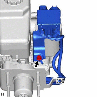
REMOVE NO. 1 BRAKE ACTUATOR TUBE
-
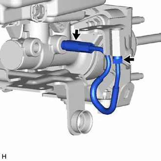
Using a union nut wrench, disconnect the No. 1 brake actuator tube from the brake master cylinder sub-assembly.
Note
-
Do not kink or damage the No. 1 brake actuator tube.
-
Do not allow any foreign matter such as dirt or dust to enter the No. 1 brake actuator tube from the connecting parts.
-
-
-
REMOVE BRAKE STROKE SIMULATOR BRACKET
-
Remove the 3 bolts and brake stroke simulator bracket from the brake master cylinder sub-assembly.
-
-
REMOVE BRAKE MASTER CYLINDER RESERVOIR ASSEMBLY
-
Mount the brake master cylinder sub-assembly in a vise.
Note
Place aluminum plates on the vise to prevent damage to the brake master cylinder sub-assembly.
-
Using a pin punch and hammer, remove the pin from the brake master cylinder reservoir assembly.
-
Remove the brake master cylinder reservoir assembly from the brake master cylinder body.
-
-
REMOVE BRAKE MASTER CYLINDER RESERVOIR FILLER CAP ASSEMBLY
-
REMOVE BRAKE MASTER CYLINDER RESERVOIR STRAINER
-
REMOVE MASTER CYLINDER RESERVOIR GROMMET
-
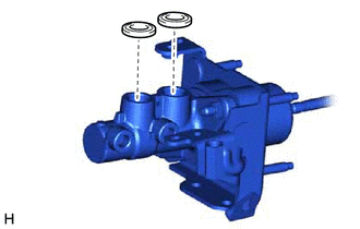
Remove the 2 master cylinder reservoir grommets from the brake master cylinder body.
-
-
REMOVE MASTER CYLINDER PUSH ROD CLEVIS
-
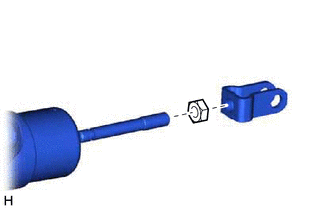
Loosen the lock nut and remove the master cylinder push rod clevis and lock nut.
Tech Tips
Measuring the protrusion of the push rod from the master cylinder push rod clevis in advance makes it easier to adjust the brake pedal height after the brake master cylinder sub-assembly is installed.
-