BRAKE CONTROL POWER SUPPLY REMOVAL
CAUTION / NOTICE / HINT
The necessary procedures (adjustment, calibration, initialization, or registration) that must be performed after parts are removed, installed, or replaced during brake control power supply with bracket assembly removal/installation are shown below.
| Replaced Part or Performed Procedure | Necessary Procedure | Effect/Inoperative Function when Necessary Procedure not Performed | Link |
|---|---|---|---|
| Battery terminal is disconnected/reconnected | Memorize steering angle neutral point | LKA/LDA system | |
| Pre-collision system | |||
| Parking assist monitor system | |||
| Steering sensor zero point calibration | Variable gear ratio steering system |
CAUTION / NOTICE / HINT
Note
While the battery is connected, even if the engine switch is off, the brake control system activates when the brake pedal is depressed or the door courtesy switch turns on. Therefore during servicing of the brake system components, do not operate the brake pedal and open/close the doors while the battery is connected.
PROCEDURE
-
PRECAUTION
Note
After turning the engine switch off, waiting time may be required before disconnecting the cable from the battery terminal. Therefore, make sure to read the disconnecting the cable from the battery terminal notice before proceeding with work.
-
DISCONNECT CABLE FROM NEGATIVE BATTERY TERMINAL
-
REMOVE LUGGAGE COMPARTMENT TRIM COVER INNER LH
-
REMOVE NO. 1 DECK BOARD BRACKET LH
-
Remove the bolt, nut and No. 1 deck board bracket LH.
-
-
REMOVE FUEL PUMP CONTROL ECU BRACKET
CAUTION:
After removing the brake control power supply with bracket assembly from the vehicle, there may be an electrical charge left in the internal capacitor. If planning to inspect the inside of the brake control power supply with bracket assembly, leave it as is for more than 24 hours (to discharge it) after removing it from the vehicle. Then, perform the inspection.
-
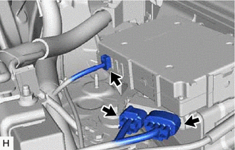
Disconnect the brake control power supply connector.
-
Disconnect the 2 fuel pump control ECU connectors.
-
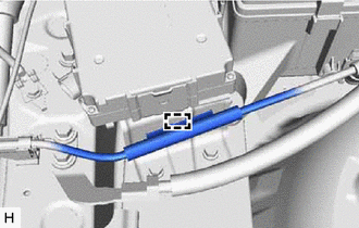
Detach the clamp
-
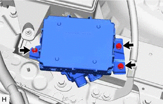
Remove the 2 bolts, nut and fuel pump control ECU bracket from the vehicle body.
-
-
REMOVE BRAKE CONTROL POWER SUPPLY WITH BRACKET ASSEMBLY
-
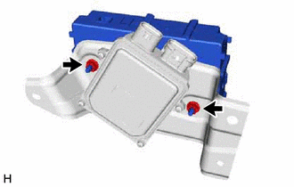
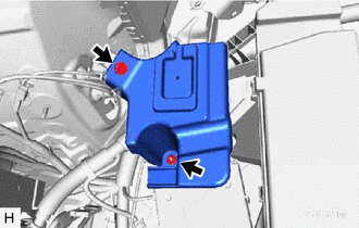
Remove the 2 nuts and brake control power supply with bracket assembly from the fuel pump control ECU bracket.
-