BRAKE ACTUATOR(for RHD) ON-VEHICLE INSPECTION

PROCEDURE
-
INSPECT BRAKE ACTUATOR OPERATION
-
Connect the GTS to the DLC3 with the engine switch off, the shift lever in P and the parking brake applied.
-
Turn the engine switch on (IG) and turn the GTS on.
-
Check the solenoid valve (SLA##, SLR##, SMC1, SMC2).
-
Enter the following menus: Chassis / ABS/VSC/TRAC / Active Test / Actuator Air Bleeding Pattern.
Chassis > ABS/VSC/TRAC > Active TestActive Test Display Actuator Air Bleeding Pattern Data List Display Master Cylinder Sensor Master Cylinder Sensor2 FR W/C Sensor FL W/C Sensor RR W/C Sensor RL W/C Sensor -
Select "Master Cylinder Sensor", "Master Cylinder Sensor 2", "FR W/C Sensor", "FL W/C Sensor", "RR W/C Sensor" and "RL W/C Sensor".
-
Turn "Actuator Air Bleeding Pattern" on and check the output voltage.
Note
Do not depress the brake pedal.
Tech Tips
-
It takes approximately 70 seconds to complete the check.
-
The sensors will be checked one by one within the 70 second time period.
-
If the voltage is not within the specified range, troubleshoot the electronically controlled brake system.
-
-
Check the FR W/C Sensor output voltage.
Standard Voltage Sensor After starting check 10 to 20 sec. after starting check Master Cylinder Sensor 0.3 to 0.7 V 0.3 to 0.7 V Master Cylinder Sensor 2 0.3 to 0.7 V 0.3 to 0.7 V FR W/C Sensor 2.5 to 4.5 V 0.3 to 0.7 V FL W/C Sensor 0.3 to 0.7 V 0.3 to 0.7 V RR W/C Sensor 0.3 to 0.7 V 0.3 to 0.7 V RL W/C Sensor 0.3 to 0.7 V 0.3 to 0.7 V -
Check the FL W/C Sensor output voltage.
Standard Voltage Sensor After starting check 10 to 20 sec. after starting check Master Cylinder Sensor 0.3 to 0.7 V 0.3 to 0.7 V Master Cylinder Sensor 2 0.3 to 0.7 V 0.3 to 0.7 V FR W/C Sensor 0.3 to 0.7 V 0.3 to 0.7 V FL W/C Sensor 2.5 to 4.5 V 0.3 to 0.7 V RR W/C Sensor 0.3 to 0.7 V 0.3 to 0.7 V RL W/C Sensor 0.3 to 0.7 V 0.3 to 0.7 V -
Check the RR W/C Sensor output voltage.
Standard Voltage Sensor After starting check 10 to 20 sec. after starting check Master Cylinder Sensor 0.3 to 0.7 V 0.3 to 0.7 V Master Cylinder Sensor 2 0.3 to 0.7 V 0.3 to 0.7 V FR W/C Sensor 0.3 to 0.7 V 0.3 to 0.7 V FL W/C Sensor 0.3 to 0.7 V 0.3 to 0.7 V RR W/C Sensor 2.5 to 4.5 V 0.3 to 0.7 V RL W/C Sensor 0.3 to 0.7 V 0.3 to 0.7 V -
Check the RL W/C Sensor output voltage.
Standard Voltage Sensor After starting check 10 to 20 sec. after starting check Master Cylinder Sensor 0.3 to 0.7 V 0.3 to 0.7 V Master Cylinder Sensor 2 0.3 to 0.7 V 0.3 to 0.7 V FR W/C Sensor 0.3 to 0.7 V 0.3 to 0.7 V FL W/C Sensor 0.3 to 0.7 V 0.3 to 0.7 V RR W/C Sensor 0.3 to 0.7 V 0.3 to 0.7 V RL W/C Sensor 2.5 to 4.5 V 0.3 to 0.7 V
-
-
Check the changeover solenoid valves (SMC1, SMC2).
-
Enter the following menus: Chassis / ABS/VSC/TRAC / Active test / ECB (Electronically Controlled Brake System) Control Invalid.
Chassis > ABS/VSC/TRAC > Active TestActive Test Display ECB Control Invalid Data List Display Master Cylinder Sensor Master Cylinder Sensor2 FR W/C Sensor FL W/C Sensor -
Select "Master Cylinder Sensor", "Master Cylinder Sensor 2", "FR W/C Sensor" and "FL W/C Sensor".
-
Turn "ECB (Electronically Controlled Brake System) Control Invalid" on, and check the output voltage by depressing the brake pedal.
Standard Voltage Difference in output voltage between "Master Cylinder Sensor" and "FR W/C Sensor" is less than 0.4 V. Difference in output voltage between "Master Cylinder Sensor 2" and "FL W/C Sensor" is less than 0.4 V. -
After inspection, turn "ECB (Electronically Controlled Brake System) Control Invalid" off.
-
-
-
INSPECT PRESSURE SENSOR OPERATION
-
Check the battery voltage.
Standard voltage 11 to 14 V (with the engine stopped) -
Set SST and a pedal effort gauge.
-
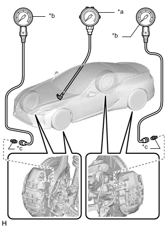
*a Pedal Effort Gauge *b SST (LSPV Gauge) *c SST (No. 1 Nipple) Set SST and a pedal effort gauge.
- SST
- 09709-29018 ( 09709-00060 )
-
Bleed air from SST (LSPV gauge).
-
Connect the GTS to the DLC3 with the engine switch off, the shift lever in P and the parking brake applied.
-
Turn the engine switch on (IG) and turn the GTS on.
-
Clear the DTCs.
-
-
Check the wheel cylinder pressure sensor and master cylinder pressure sensor.
-
Enter the following menus: Chassis / ABS/VSC/TRAC / Data List / Master Cylinder Sensor, Master Cylinder Sensor 2, FR W/C Sensor, FL W/C Sensor, RR W/C Sensor, and RL W/C Sensor.
Chassis > ABS/VSC/TRAC > Data ListTester Display Master Cylinder Sensor Master Cylinder Sensor2 FR W/C Sensor FL W/C Sensor RR W/C Sensor RL W/C Sensor -
Check the output voltage and hydraulic pressure by depressing the brake pedal.
Standard Value Brake Effort Master Cylinder Sensor Master Cylinder Sensor 2 200 N (20 kgf, 45.0 lbf) 0.69 to 2.09 V 0.67 to 2.07 V 500 N (51 kgf, 112.4 lbf) 1.48 to 1.88 V 1.46 to 1.86 V Brake Effort Front Right Wheel Hydraulic Pressure FR W/C Sensor 50 N (5 kgf, 11.2 lbf) 0.76 to 2.76 MPa (7.8 to 28.1 kgf/cm2, 111 to 400 psi)
0.66 to 1.06 V 100 N (10 kgf, 22.5 lbf) 3.60 to 5.60 MPa (36.8 to 57.1 kgf/cm2, 522 to 812 psi)
1.24 to 1.64 V 150 N (15 kgf, 33.7 lbf) 4.22 to 6.22 MPa (43.1 to 63.4 kgf/cm2, 612 to 901 psi)
1.37 to 1.77 V 200 N (20 kgf, 45.0 lbf) 4.22 to 6.22 MPa (43.1 to 63.4 kgf/cm2, 612 to 901 psi)
1.37 to 1.77 V Brake Effort Front Left Wheel Hydraulic Pressure FL W/C Sensor 50 N (5 kgf, 11.2 lbf) 0.76 to 2.76 MPa (7.8 to 28.1 kgf/cm2, 111 to 400 psi)
0.66 to 1.06 V 100 N (10 kgf, 22.5 lbf) 3.60 to 5.60 MPa (36.8 to 57.1 kgf/cm2, 522 to 812 psi)
1.24 to 1.64 V 150 N (15 kgf, 33.7 lbf) 4.22 to 6.22 MPa (43.1 to 63.4 kgf/cm2, 612 to 901 psi)
1.37 to 1.77 V 200 N (20 kgf, 45.0 lbf) 4.22 to 6.22 MPa (43.1 to 63.4 kgf/cm2, 612 to 901 psi)
1.37 to 1.77 V Brake Effort Rear Right Wheel Hydraulic Pressure RR W/C Sensor 50 N (5 kgf, 11.2 lbf) 0.76 to 2.76 MPa (7.8 to 28.1 kgf/cm2, 111 to 400 psi)
0.66 to 1.06 V 100 N (10 kgf, 22.5 lbf) 3.60 to 5.60 MPa (36.8 to 57.1 kgf/cm2, 522 to 812 psi)
1.24 to 1.64 V 150 N (15 kgf, 33.7 lbf) 4.22 to 6.22 MPa (43.1 to 63.4 kgf/cm2, 612 to 901 psi)
1.37 to 1.77 V 200 N (20 kgf, 45.0 lbf) 4.22 to 6.22 MPa (43.1 to 63.4 kgf/cm2, 612 to 901 psi)
1.37 to 1.77 V Brake Effort Rear Left Wheel Hydraulic Pressure RL W/C Sensor 50 N (5 kgf, 11.2 lbf) 0.76 to 2.76 MPa (7.8 to 28.1 kgf/cm2, 111 to 400 psi)
0.66 to 1.06 V 100 N (10 kgf, 22.5 lbf) 3.60 to 5.60 MPa (36.8 to 57.1 kgf/cm2, 522 to 812 psi)
1.24 to 1.64 V 150 N (15 kgf, 33.7 lbf) 4.22 to 6.22 MPa (43.1 to 63.4 kgf/cm2, 612 to 901 psi)
1.37 to 1.77 V 200 N (20 kgf, 45.0 lbf) 4.22 to 6.22 MPa (43.1 to 63.4 kgf/cm2, 612 to 901 psi)
1.37 to 1.77 V If the result is not as specified, troubleshoot the electronically controlled brake system.
-
-
Check the accumulator sensor.
-
Move the shift lever to P. Apply the parking brake and connect the GTS to the DLC3.
-
Turn the engine switch on (IG).
-
Turn the GTS on.
-
Enter the following menus: Chassis / ABS/VSC/TRAC / Data List / Accumulator Sensor.
Chassis > ABS/VSC/TRAC > Data ListTester Display Accumulator Sensor -
Depress the brake pedal 4 or 5 times and operate the booster pump motor.
-
After confirming that the booster pump motor has stopped, check the output voltage.
Standard Voltage 2.6 to 3.8 V If the result is not as specified, troubleshoot the electronically controlled brake system.
-
-
Remove SST and the pedal effort gauge.
-
Remove SST and the pedal effort gauge, and bleed the brake line.
-
-