ELECTRONICALLY CONTROLLED BRAKE SYSTEM, Diagnostic DTC:C1252/52, C1253/53
| DTC Code | DTC Name |
|---|---|
| C1252/52 | Brake Booster Pump Motor on Time Abnormally Long |
| C1253/53 | Pump Motor Relay Malfunction |
DESCRIPTION
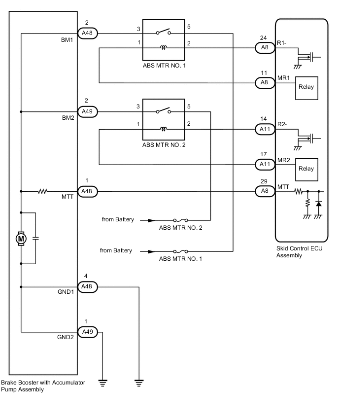
The skid control ECU assembly detects decreases in the accumulator pressure according to the data from the accumulator pressure sensor, and then starts and stops the pump motor by operating the ABS motor relay.
The skid control ECU assembly usually drives the ABS motor relay 1 for electronically controlled brake system control, and the ABS motor relay 2 for ABS control. If either of them is malfunctioning, the other will substitute.
| DTC No. | Detection Item | INF Code | DTC Detection Condition | Trouble Area | Note |
|---|---|---|---|---|---|
| C1252/52 | Brake Booster Pump Motor on Time Abnormally Long | 130 | ABS motor relay is on for at least 3 minutes. |
|
Electronically controlled brake system DTC |
| C1253/53 | Pump Motor Relay Malfunction | 134 138 140 |
|
|
Electronically controlled brake system DTC |
| DTC No. | Brake warning light / yellow (minor malfunction) code | ABS warning light code | Slip indicator light code | Brake hold standby indicator light code |
|---|---|---|---|---|
| C1252 | 52 | 42 | 45 | 21 |
| C1253 | 53 | 42 | 45 | 21 |
WIRING DIAGRAM
CAUTION / NOTICE / HINT
Note
-
When replacing the skid control ECU assembly or brake actuator assembly, perform initialization and calibration of the linear solenoid valve.
-
Inspect the fuses for circuits related to this system before performing the following procedure.
PROCEDURE
-
PERFORM ACTIVE TEST USING GTS (ABS MOTOR RELAY)
-
Connect the GTS to the DLC3.
-
Turn the engine switch on (IG).
-
Select the Active Test on the GTS.
Chassis > ABS/VSC/TRC > Active TestTester Display Measurement Item Control Range Diagnostic Note ECB Motor Relay ABS motor relay 1 Relay ON/OFF
-
Operation sound of relay (clicking sound) and pump motor can be heard
-
ECB: Electronically Controlled Brake System
ECB Motor Relay2 ABS motor relay 2 Relay ON/OFF
-
Operation sound of relay (clicking sound) and pump motor can be heard
-
ECB: Electronically Controlled Brake System
Chassis > ABS/VSC/TRC > Active TestTester Display ECB Motor Relay
-
ECB: Electronically Controlled Brake System
Chassis > ABS/VSC/TRC > Active TestTester Display ECB Motor Relay2
-
ECB: Electronically Controlled Brake System
-
-
Check the operation sound of the ABS motor relay and motor when operating it using the GTS.
OK The operation sound of the ABS motor relay and motor should be heard. Result Proceed to OK NG
NG 
INSPECT ABS MOTOR RELAY Click here
OK 
-
-
INSPECT BRAKE BOOSTER WITH ACCUMULATOR PUMP ASSEMBLY
-
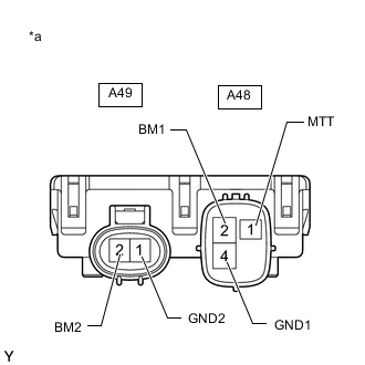
*a Component without harness connected
(Brake Booster with Accumulator Pump Assembly)
Make sure that there is no looseness at the locking part and the connecting part of the connectors.
-
Disconnect the A48 and A49 brake booster with accumulator pump assembly connectors.
-
Measure the resistance according to the value(s) in the table below.
Standard Resistance Tester Connection Condition Specified Condition A48-2 (BM1) - A48-4 (GND1) Always Below 10 Ω A49-2 (BM2) - A49-1 (GND2) Always Below 10 Ω A48-2 (BM1) - A49-2 (BM2) Always Below 1 Ω A48-4 (GND1) - A49-1 (GND2) Always Below 1 Ω A48-2 (BM1) - A48-1 (MTT) Always 950 to 1050 Ω A49-2 (BM2) - A48-1 (MTT) Always 950 to 1050 Ω Result Proceed to OK NG
NG 
REPLACE BRAKE BOOSTER WITH ACCUMULATOR PUMP ASSEMBLY Click here
OK
-
-
CHECK HARNESS AND CONNECTOR (SKID CONTROL ECU ASSEMBLY - BRAKE BOOSTER WITH ACCUMULATOR PUMP ASSEMBLY)
-
Make sure that there is no looseness at the locking part and the connecting part of the connector.
-
Disconnect the A8 skid control ECU assembly connector.
-
Measure the resistance according to the value(s) in the table below.
Standard Resistance Tester Connection Condition Specified Condition A8-29 (MTT) - A48-1 (MTT) Always Below 1 Ω A8-29 (MTT) or A48-1 (MTT) - Body ground Always 10 kΩ or higher A48-4 (GND1) - Body ground Always Below 1 Ω A49-1 (GND2) - Body ground Always Below 1 Ω Result Proceed to OK NG
NG
REPAIR OR REPLACE HARNESS OR CONNECTOR
OK
-
-
READ VALUE USING GTS (ACCUMULATOR PRESSURE SENSOR)
-
Reconnect the A8 skid control ECU assembly connector.
-
Reconnect the A48 and A49 brake booster with accumulator pump assembly connectors.
-
Connect the GTS to the DLC3.
-
Turn the engine switch on (IG).
-
Select the Data List on the GTS.
Chassis > ABS/VSC/TRC > Data ListTester Display Measurement Item Range Normal Condition Diagnostic Note Accumulator Sensor Accumulator pressure sensor Min.: 0.00 V, Max.: 5.00 V Specified value: 2.60 to 3.80 V When brake fluid is stored in the accumulator: Accumulator pressure changes in accordance with volume of fluid stored in the accumulator
Chassis > ABS/VSC/TRC > Data ListTester Display Accumulator Sensor -
Depress the brake pedal 4 or 5 times and operate the pump motor.
-
Wait for 30 seconds without depressing the brake pedal.
-
Check that the accumulator pressure sensor output value change is within the specified range.
OK Accumulator pressure sensor output value change is less than 0.20 V. Tech Tips
-
This inspection is performed to determine if a long-term power malfunction occurred when low pressure is detected due to a defective sensor, an internal leak in the brake actuator assembly, or deterioration of the accumulator.
-
External brake fluid leaks are suspected if the fluid level drops inside the brake master cylinder reservoir assembly.
Result Proceed to OK NG -
NG
PERFORM ACTIVE TEST USING GTS (SOLENOID VALVE) Click here
OK
-
-
RECONFIRM DTC
-
Clear the DTCs.
Chassis > ABS/VSC/TRC > Clear DTCs -
Turn the engine switch off.
-
Turn the engine switch on (IG).
-
Check if the same DTC is output.
Chassis > ABS/VSC/TRC > Trouble CodesResult Result Proceed to DTCs C1252/52 and C1253/53 are not output. A DTCs C1252/52 and/or C1253/53 are output. B
A
USE SIMULATION METHOD TO CHECK Click here
B
REPLACE SKID CONTROL ECU ASSEMBLY for RHD: Click here
REPLACE SKID CONTROL ECU ASSEMBLY for LHD: Click here -
-
PERFORM ACTIVE TEST USING GTS (SOLENOID VALVE)
-
Select the Active Test on the GTS.
Chassis > ABS/VSC/TRC > Active TestTester Display Measurement Item Control Range Diagnostic Note ECB Solenoid (SMC1) Master cut solenoid (SMC1) Solenoid ON/OFF ECB: Electronically Controlled Brake System
Chassis > ABS/VSC/TRC > Active TestTester Display ECB Solenoid (SMC1)
-
ECB: Electronically Controlled Brake System
Tech Tips
The Active Test can be performed when the following conditions are met.
-
ABS main relay is on.
-
Shift position is in P.
-
Parking brake is applied.
-
Vehicle speed is 0 km/h (0 mph).
-
-
Perform the Active Test of the solenoid using the GTS.
-
Select the Data List on the GTS.
Chassis > ABS/VSC/TRC > Data ListTester Display Measurement Item Range Normal Condition Diagnostic Note FR W/C Sensor Front wheel cylinder pressure sensor RH Min.: 0.00 V, Max.: 5.00 V Brake pedal released: 0.30 to 0.70 V Reading increases when brake pedal is depressed
Chassis > ABS/VSC/TRC > Data ListTester Display FR W/C Sensor -
Check that the output value of the wheel cylinder pressure sensor does not increase.
OK The output value of the wheel cylinder pressure sensor does not increase. Tech Tips
If output value increases, there may be brake fluid leaks in the brake actuator assembly.
Result Result Proceed to The output values of the wheel cylinder pressure sensors do not increase. A The output value of the wheel cylinder pressure sensor increases. B
B
REPLACE BRAKE ACTUATOR ASSEMBLY for RHD: Click here
REPLACE BRAKE ACTUATOR ASSEMBLY for LHD: Click hereA
-
-
PERFORM ACTIVE TEST USING GTS (SOLENOID VALVE)
-
Select the Active Test on the GTS.
Chassis > ABS/VSC/TRC > Active TestTester Display Measurement Item Control Range Diagnostic Note ECB Solenoid (SMC2) Master cut solenoid (SMC2) Solenoid ON/OFF ECB: Electronically Controlled Brake System
Chassis > ABS/VSC/TRC > Active TestTester Display ECB Solenoid (SMC2)
-
ECB: Electronically Controlled Brake System
Tech Tips
The Active Test can be performed when the following conditions are met.
-
ABS main relay is on.
-
Shift position is in P.
-
Parking brake is applied.
-
Vehicle speed is 0 km/h (0 mph).
-
-
Perform the Active Test of the solenoid using the GTS.
-
Select the Data List on the GTS.
Chassis > ABS/VSC/TRC > Data ListTester Display Measurement Item Range Normal Condition Diagnostic Note FL W/C Sensor Front wheel cylinder pressure sensor LH Min.: 0.00 V, Max.: 5.00 V Brake pedal released: 0.30 to 0.70 V Reading increases when brake pedal is depressed
Chassis > ABS/VSC/TRC > Data ListTester Display FL W/C Sensor -
Check that the output value of the wheel cylinder pressure sensor does not increase.
OK The output value of the wheel cylinder pressure sensor does not increase. Tech Tips
If output value increases, there may be brake fluid leaks in the brake actuator assembly.
Result Result Proceed to The output values of the wheel cylinder pressure sensors do not increase. A The output value of the wheel cylinder pressure sensor increases. B
B
REPLACE BRAKE ACTUATOR ASSEMBLY for RHD: Click here
REPLACE BRAKE ACTUATOR ASSEMBLY for LHD: Click hereA
-
-
PERFORM ACTIVE TEST USING GTS (SOLENOID VALVE)
-
Select the Active Test on the GTS.
Chassis > ABS/VSC/TRC > Active TestTester Display Measurement Item Control Range Diagnostic Note ECB Solenoid (SLRRR) Linear solenoid (RRR) valve Valve close ON/OFF ECB: Electronically Controlled Brake System
Chassis > ABS/VSC/TRC > Active TestTester Display ECB Solenoid (SLRRR)
-
ECB: Electronically Controlled Brake System
Tech Tips
The Active Test can be performed when the following conditions are met.
-
ABS main relay is on.
-
Shift position is in P.
-
Parking brake is applied.
-
Vehicle speed is 0 km/h (0 mph).
-
-
Perform the Active Test of the solenoid using the GTS.
-
Select the Data List on the GTS.
Chassis > ABS/VSC/TRC > Data ListTester Display Measurement Item Range Normal Condition Diagnostic Note RR W/C Sensor Rear wheel cylinder pressure sensor RH Min.: 0.00 V, Max.: 5.00 V Brake pedal released: 0.30 to 0.70 V Reading increases when brake pedal is depressed
Chassis > ABS/VSC/TRC > Data ListTester Display RR W/C Sensor -
Check that the output value of the wheel cylinder pressure sensor does not increase.
OK The output value of the wheel cylinder pressure sensor does not increase. Tech Tips
If output value increases, there may be brake fluid leaks in the brake actuator assembly.
Result Result Proceed to The output values of the wheel cylinder pressure sensors do not increase. A The output value of the wheel cylinder pressure sensor increases. B
B
REPLACE BRAKE ACTUATOR ASSEMBLY for RHD: Click here
REPLACE BRAKE ACTUATOR ASSEMBLY for LHD: Click hereA
-
-
PERFORM ACTIVE TEST USING GTS (SOLENOID VALVE)
-
Select the Active Test on the GTS.
Chassis > ABS/VSC/TRC > Active TestTester Display Measurement Item Control Range Diagnostic Note ECB Solenoid (SLRRL) Linear solenoid (RLR) valve Valve close ON/OFF ECB: Electronically Controlled Brake System
Chassis > ABS/VSC/TRC > Active TestTester Display ECB Solenoid (SLRRL)
-
ECB: Electronically Controlled Brake System
Tech Tips
The Active Test can be performed when the following conditions are met.
-
ABS main relay is on.
-
Shift position is in P.
-
Parking brake is applied.
-
Vehicle speed is 0 km/h (0 mph).
-
-
Perform the Active Test of the solenoid using the GTS.
-
Select the Data List on the GTS.
Chassis > ABS/VSC/TRC > Data ListTester Display Measurement Item Range Normal Condition Diagnostic Note RL W/C Sensor Rear wheel cylinder pressure sensor LH Min.: 0.00 V, Max.: 5.00 V Brake pedal released: 0.30 to 0.70 V Reading increases when brake pedal is depressed
Chassis > ABS/VSC/TRC > Data ListTester Display RL W/C Sensor -
Check that the output value of the wheel cylinder pressure sensor does not increase.
OK The output value of the wheel cylinder pressure sensor does not increase. Tech Tips
If output value increases, there may be brake fluid leaks in the brake actuator assembly.
Result Result Proceed to The output values of the wheel cylinder pressure sensors do not increase. A The output value of the wheel cylinder pressure sensor increases. B
A
REPLACE BRAKE BOOSTER WITH ACCUMULATOR PUMP ASSEMBLY Click here
B
REPLACE BRAKE ACTUATOR ASSEMBLY for RHD: Click here
REPLACE BRAKE ACTUATOR ASSEMBLY for LHD: Click here -
-
INSPECT ABS MOTOR RELAY
-
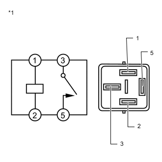
*1 ABS Motor Relay (ABS MTR NO. 1 or ABS MTR NO. 2 relay) Remove the ABS motor relay (ABS MTR NO. 1 and ABS MTR NO. 2 relays).
-
Measure the resistance according to the value(s) in the table below.
Standard Resistance Tester Connection Condition Specified Condition 3 - 5 Voltage is not applied between terminals 1 and 2 10 kΩ or higher 3 - 5 Voltage is applied between terminals 1 and 2 Below 1 Ω Result Proceed to OK NG
NG
REPLACE ABS MOTOR RELAY
OK
-
-
INSPECT NO. 1 ENGINE ROOM RELAY BLOCK AND JUNCTION BLOCK (POWER SOURCE TERMINAL)
-
Figure 1. for RHD:
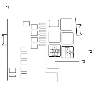
*1 NO. 1 Engine Room Relay Block and Junction Block *2 ABS MTR NO. 1 Relay *3 ABS MTR NO. 2 Relay Figure 2. for LHD:
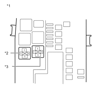
*1 NO. 1 Engine Room Relay Block and Junction Block *2 ABS MTR NO. 1 Relay *3 ABS MTR NO. 2 Relay Measure the voltage according to the value(s) in the table below.
Standard Voltage Tester Connection Condition Specified Condition ABS MTR NO. 1 relay terminal 5 - Body ground Always 11 to 14 V ABS MTR NO. 2 relay terminal 5 - Body ground Always 11 to 14 V Result Proceed to OK NG
NG
REPAIR OR REPLACE HARNESS OR CONNECTOR (POWER SOURCE CIRCUIT)
OK
-
-
CHECK HARNESS AND CONNECTOR (BRAKE BOOSTER WITH ACCUMULATOR PUMP ASSEMBLY - NO. 1 ENGINE ROOM RELAY BLOCK AND JUNCTION BLOCK)
-
Make sure that there is no looseness at the locking part and the connecting part of the connector.
-
Disconnect the A48 and A49 brake booster with accumulator pump assembly connectors.
-
Measure the resistance according to the value(s) in the table below.
Standard Resistance Tester Connection Condition Specified Condition A48-2 (BM1) - ABS MTR NO. 1 relay terminal 3 Always Below 1 Ω A48-2 (BM1) or ABS MTR NO. 1 relay terminal 3 - Body ground Always 10 kΩ or higher A49-2 (BM2) - ABS MTR NO. 2 relay terminal 3 Always Below 1 Ω A49-2 (BM2) or ABS MTR NO. 2 relay terminal 3 - Body ground Always 10 kΩ or higher Result Proceed to OK NG
NG
REPAIR OR REPLACE HARNESS OR CONNECTOR
OK
-
-
CHECK HARNESS AND CONNECTOR (SKID CONTROL ECU ASSEMBLY - NO. 1 ENGINE ROOM RELAY BLOCK AND JUNCTION BLOCK)
-
Make sure that there is no looseness at the locking part and the connecting part of the connectors.
-
Disconnect the A11 and A8 skid control ECU assembly connectors.
-
Measure the resistance according to the value(s) in the table below.
Standard Resistance Tester Connection Condition Specified Condition A8-24 (R1-) - ABS MTR NO. 1 relay terminal 2 Always Below 1 Ω A8-24 (R1-) or ABS MTR NO. 1 relay terminal 2 - Body ground Always 10 kΩ or higher A8-11 (MR1) - ABS MTR NO. 1 relay terminal 1 Always Below 1 Ω A8-11 (MR1) or ABS MTR NO. 1 relay terminal 1 - Body ground Always 10 kΩ or higher A11-14 (R2-) - ABS MTR NO. 2 relay terminal 2 Always Below 1 Ω A11-14 (R2-) or ABS MTR NO. 2 relay terminal 2 - Body ground Always 10 kΩ or higher A11-17 (MR2) - ABS MTR NO. 2 relay terminal 1 Always Below 1 Ω A11-17 (MR2) or ABS MTR NO. 2 relay terminal 1 - Body ground Always 10 kΩ or higher Result Proceed to OK NG
OK
REPLACE SKID CONTROL ECU ASSEMBLY for RHD: Click here
REPLACE SKID CONTROL ECU ASSEMBLY for LHD: Click hereNG
REPAIR OR REPLACE HARNESS OR CONNECTOR
-