ELECTRONICALLY CONTROLLED BRAKE SYSTEM, Diagnostic DTC:C1235/35, C1236/36, C1238/38, C1239/39
| DTC Code | DTC Name |
|---|---|
| C1235/35 | Foreign Object is Attached on Tip of Front Speed Sensor RH |
| C1236/36 | Foreign Object is Attached on Tip of Front Speed Sensor LH |
| C1238/38 | Foreign Object is Attached on Tip of Rear Speed Sensor RH |
| C1239/39 | Foreign Object is Attached on Tip of Rear Speed Sensor LH |
DESCRIPTION
When foreign matter adheres to a speed sensor tip or speed sensor rotor, these DTCs are stored. The presence of foreign matter can be judged when an abnormal waveform is received from a sensor.
These DTCs may also be detected when a malfunction occurs in the connector terminals or wire harness of the speed sensor circuit.
When C1464/31, C1465/32, C1466/33, and/or C1467/34 are output together with C1235/35, C1236/36, C1238/38, and/or C1239/39, inspect and repair the trouble areas indicated by C1464/31, C1465/32, C1466/33, and/or C1467/34 first.
| DTC No. | Detection Item | INF Code | DTC Detection Condition | Trouble Area | Note |
|---|---|---|---|---|---|
| C1235/35 | Foreign Object is Attached on Tip of Front Speed Sensor RH | 302 | Either of the following is detected:
|
|
ABS DTC |
| C1236/36 | Foreign Object is Attached on Tip of Front Speed Sensor LH | 303 | Either of the following is detected:
|
|
ABS DTC |
| C1238/38 | Foreign Object is Attached on Tip of Rear Speed Sensor RH | 304 | Either of the following is detected:
|
|
ABS DTC |
| C1239/39 | Foreign Object is Attached on Tip of Rear Speed Sensor LH | 305 | Either of the following is detected:
|
|
ABS DTC |
| DTC No. | Brake warning light / yellow (minor malfunction) code | ABS warning light code | Slip indicator light code | Brake hold standby indicator light code |
|---|---|---|---|---|
| C1235 | 36 | 35 | 43 | 21 |
| C1236 | 36 | 36 | 43 | 21 |
| C1238 | 36 | 38 | 43 | 21 |
| C1239 | 36 | 39 | 43 | 21 |
Tech Tips
-
DTC C1235/35 is for the front speed sensor RH.
-
DTC C1236/36 is for the front speed sensor LH.
-
DTC C1238/38 is for the rear speed sensor RH.
-
DTC C1239/39 is for the rear speed sensor LH.
WIRING DIAGRAM
Refer to DTCs C1464/31, C1465/32, C1466/33 and C1467/34.
for Front: Click here
for Rear: Click here
CAUTION / NOTICE / HINT
Note
When replacing the skid control ECU assembly, perform initialization and calibration of the linear solenoid valve.
PROCEDURE
-
CHECK DTC
-
Check the output DTCs .
Chassis > ABS/VSC/TRC > Trouble CodesResult Result Proceed to DTC C1235/35 or C1236/36 is output. A DTC C1238/38 or C1239/39 is output. B DTCs C1464/31 or C1465/32 are output simultaneously. C DTCs C1466/33 or C1467/34 are output simultaneously. D
B 
INSPECT SKID CONTROL SENSOR WIRE Click here
C 
REPAIR CIRCUITS INDICATED BY OUTPUT DTCS Click here
D
REPAIR CIRCUITS INDICATED BY OUTPUT DTCS Click here
A 
-
-
INSPECT FRONT SKID CONTROL SENSOR WIRE
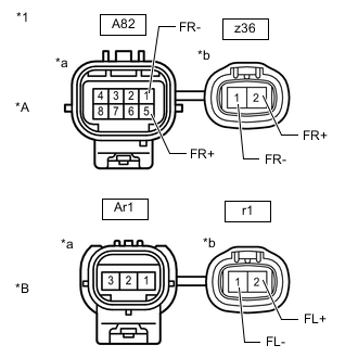
*A for RH *B for LH *1 Front Skid Control Sensor Wire *a Front view of wire harness connector
(to Vehicle Side Connector)
*b Front view of wire harness connector
(to Sensor Side Connector)
-
Make sure that there is no looseness at the locking part and the connecting part of the connectors.
-
Remove the front skid control sensor wire.
-
Measure the resistance according to the value(s) in the table below.
Standard Resistance for RH Tester Connection Condition Specified Condition z36-2 (FR+) - A82-5 (FR+) Always Below 1 Ω z36-2 (FR+) or A82-5 (FR+) - Body ground and other terminals Always 10 MΩ or higher z36-1 (FR-) - A82-1 (FR-) Always Below 1 Ω z36-1 (FR-) or A82-1 (FR-) - Body ground and other terminals Always 10 MΩ or higher for LH Tester Connection Condition Specified Condition r1-2 (FL+) - Ar1-3 Always Below 1 Ω r1-2 (FL+) or Ar1-3 - Body ground and other terminals Always 10 MΩ or higher r1-1 (FL-) - Ar1-1 Always Below 1 Ω r1-1 (FL-) or Ar1-1 - Body ground and other terminals Always 10 MΩ or higher Result Proceed to OK NG
NG
REPLACE FRONT SKID CONTROL SENSOR WIRE Click here
OK
-
-
CHECK HARNESS AND CONNECTOR (SKID CONTROL ECU ASSEMBLY - FRONT SKID CONTROL SENSOR WIRE)
-
Make sure that there is no looseness at the locking part and the connecting part of the connector.
-
Disconnect the A8 and A10 skid control ECU assembly connectors.
-
Measure the resistance according to the value(s) in the table below.
Standard Resistance for RH Tester Connection Condition Specified Condition A8-22 (FR+) - A82-5 (FR+) Always Below 1 Ω A8-22 (FR+) or A82-5 (FR+) - Body ground Always 10 MΩ or higher A8-23 (FR-) - A82-1 (FR-) Always Below 1 Ω A8-23 (FR-) or A82-1 (FR-) - Body ground Always 10 MΩ or higher for LH Tester Connection Condition Specified Condition A10-31 (FL+) - Ar1-3 Always Below 1 Ω A10-31 (FL+) or Ar1-3 - Body ground Always 10 MΩ or higher A10-32 (FL-) - Ar1-1 Always Below 1 Ω A10-32 (FL-) or Ar1-1 - Body ground Always 10 MΩ or higher Result Proceed to OK NG
OK
REPLACE FRONT AXLE HUB SUB-ASSEMBLY Click here The front speed sensor and speed sensor rotor are incorporated into the front axle hub sub-assembly.
NG
REPAIR OR REPLACE HARNESS OR CONNECTOR
-
-
INSPECT SKID CONTROL SENSOR WIRE
-
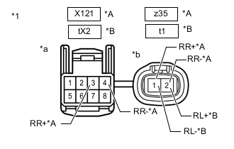
*A for RH *B for LH *1 Skid Control Sensor Wire *a Front view of wire harness connector
(to Vehicle Side Connector)
*b Front view of wire harness connector
(to Sensor Side Connector)
Make sure that there is no looseness at the locking part and the connecting part of the connectors.
-
Remove the rear skid control sensor wire.
-
Measure the resistance according to the value(s) in the table below.
Standard Resistance for RH Tester Connection Condition Specified Condition z35-1 (RR+) - X121-3 (RR+) Always Below 1 Ω z35-1 (RR+) - X121-4 (RR-) Always 10 MΩ or higher z35-1 (RR+) or X121-3 (RR+) - Body ground Always 10 MΩ or higher z35-2 (RR-) - X121-4 (RR-) Always Below 1 Ω z35-2 (RR-) - X121-3 (RR+) Always 10 MΩ or higher z35-2 (RR-) or X121-4 (RR-) - Body ground Always 10 MΩ or higher for LH Tester Connection Condition Specified Condition t1-2 (RL+) - tX2-3 Always Below 1 Ω t1-2 (RL+) - tX2-4 Always 10 MΩ or higher t1-2 (RL+) or tX2-3 - Body ground Always 10 MΩ or higher t1-1 (RL-) - tX2-4 Always Below 1 Ω t1-1 (RL-) - tX2-3 Always 10 MΩ or higher t1-1 (RL-) or tX2-4 - Body ground Always 10 MΩ or higher Result Proceed to OK NG
NG
REPLACE SKID CONTROL SENSOR WIRE Click here
OK
-
-
CHECK HARNESS AND CONNECTOR (SKID CONTROL ECU ASSEMBLY - REAR SKID CONTROL SENSOR WIRE)
-
Make sure that there is no looseness at the locking part and the connecting part of the connector.
-
Disconnect the A9 and A11 skid control ECU assembly connectors.
-
Measure the resistance according to the value(s) in the table below.
Standard Resistance for RH Tester Connection Condition Specified Condition A11-22 (RR+) - X121-3 (RR+) Always Below 1 Ω A11-22 (RR+) or X121-3 (RR+) - Body ground Always 10 MΩ or higher A11-21 (RR-) - X121-4 (RR-) Always Below 1 Ω A11-21 (RR-) or X121-4 (RR-) - Body ground Always 10 MΩ or higher for LH Tester Connection Condition Specified Condition A9-34 (RL+) - tX2-3 Always Below 1 Ω A9-34 (RL+) or tX2-3 - Body ground Always 10 MΩ or higher A9-35 (RL-) - tX2-4 Always Below 1 Ω A9-35 (RL-) or tX2-4 - Body ground Always 10 MΩ or higher Result Proceed to OK NG
NG
REPAIR OR REPLACE HARNESS OR CONNECTOR
OK
-
-
CHECK REAR SPEED SENSOR
-
Check the speed sensor tip.
OK The sensor tip is free of oil and foreign matter. Result Proceed to OK NG
NG
CLEAN REAR SPEED SENSOR
OK
-
-
CHECK REAR AXLE HUB AND BEARING ASSEMBLY
-
Check the speed sensor rotor (rear axle hub and bearing assembly).
OK The speed sensor rotor is free of scratches, oil, and foreign matter. Tech Tips
The speed sensor rotor is incorporated into the rear axle hub and bearing assembly.
Result Result Proceed to OK A Foreign matter and oil present B Damage present C
A
REPLACE REAR SPEED SENSOR Click here
B
CLEAN SPEED SENSOR ROTOR
C
REPLACE REAR AXLE HUB AND BEARING ASSEMBLY Click here
-