ELECTRONICALLY CONTROLLED BRAKE SYSTEM, Diagnostic DTC:C1202/68
| DTC Code | DTC Name |
|---|---|
| C1202/68 | Master Reservoir Level Malfunction |
DESCRIPTION
When a fluid level drop in the brake master cylinder reservoir assembly is detected, a signal is sent to the skid control ECU assembly.
| DTC No. | Detection Item | INF Code | DTC Detection Condition | Trouble Area | Note |
|---|---|---|---|---|---|
| C1202/68 | Master Reservoir Level Malfunction | 511 512 |
|
|
Electronically controlled brake system DTC |
| DTC No. | Brake warning light / yellow (minor malfunction) code | ABS warning light code | Slip indicator light code | Brake hold standby indicator light code |
|---|---|---|---|---|
| C1202 | 68 | 42 | 45 | 21 |
WIRING DIAGRAM
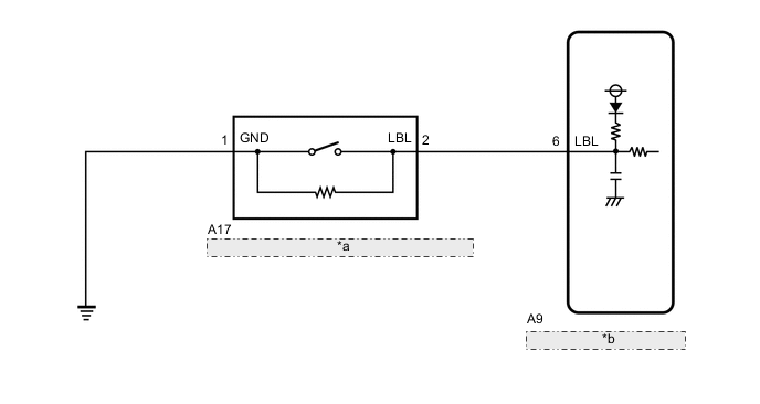
| *a | Brake Fluid Level Warning Switch (Brake Master Cylinder Reservoir Assembly) |
| *b | Skid Control ECU Assembly |
CAUTION / NOTICE / HINT
Note
When replacing the skid control ECU assembly, perform initialization and calibration of the linear solenoid valve.
PROCEDURE
-
CHECK BRAKE FLUID LEVEL
-
Check that the brake fluid level is sufficient.
Tech Tips
-
If the fluid level is low, check for fluid leaks, and repair as necessary.
-
Check for brake fluid leaks (connection between the brake booster with accumulator pump assembly, brake master cylinder reservoir assembly and the brake actuator assembly, and between the brake actuator assembly and wheel cylinders).
-
If no leaks exist, add and adjust fluid and then check that the trouble code is not output again.
OK Brake fluid level is sufficient. -
-
Check that there are no leaks from the connections between the brake booster with accumulator pump assembly and brake actuator assembly.
Tech Tips
As a visual check is very difficult, perform the check with the following procedure.
-
Bleed air from the brake actuator assembly.
-
Connect the GTS to the DLC3.
-
Turn the engine switch on (IG).
-
Select the Data List on the GTS.
Chassis > ABS/VSC/TRC > Data ListTester Display Measurement Item Range Normal Condition Diagnostic Note Accumulator Sensor Accumulator pressure sensor Min.: 0.00 V, Max.: 5.00 V Specified value: 2.60 to 3.80 V When brake fluid is stored in the accumulator: Accumulator pressure changes in accordance with volume of fluid stored in the accumulator -
Depress the brake pedal 4 or 5 times to operate the pump motor.
-
Wait for 30 seconds without depressing the brake pedal.
-
Check that the accumulator pressure sensor output value change is within the specified range.
OK Accumulator pressure sensor output value change is less than 0.20 V.
Result Proceed to OK NG -
NG 
CHECK AND REPAIR BRAKE FLUID LEAKS OR ADD FLUID
OK 
-
-
INSPECT BRAKE MASTER CYLINDER RESERVOIR ASSEMBLY
-
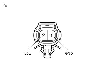
*a Component without harness connected
(Brake Fluid Level Warning Switch (Brake Master Cylinder Reservoir Assembly))
Remove the brake master cylinder reservoir filler cap and strainer.
-
Make sure that there is no looseness at the locking part and the connecting part of the connector.
-
Disconnect the A17 brake fluid level warning switch (brake master cylinder reservoir assembly) connector.
-
Measure the resistance according to the value(s) in the table below.
Tech Tips
A float is located inside the reservoir. Its position changes according to the level of brake fluid.
Standard Resistance Tester Connection Condition Specified Condition 2 (LBL) - 1 (GND) Brake fluid level warning switch (Brake master cylinder reservoir assembly) off (float up) 1.84 to 2.16 kΩ 2 (LBL) - 1 (GND) Brake fluid level warning switch (Brake master cylinder reservoir assembly) on (float down) Below 1 Ω Tech Tips
If there are no problems after completing the preceding inspection, adjust the brake fluid to the MAX level with the engine switch on (IG).
Result Proceed to OK NG
NG
REPLACE BRAKE MASTER CYLINDER RESERVOIR ASSEMBLY for RHD: Click here
REPLACE BRAKE MASTER CYLINDER RESERVOIR ASSEMBLY for LHD: Click hereOK
-
-
CHECK HARNESS AND CONNECTOR (SKID CONTROL ECU ASSEMBLY - BRAKE MASTER CYLINDER RESERVOIR ASSEMBLY)
-
Make sure that there is no looseness at the locking part and the connecting part of the connector.
-
Disconnect the A9 skid control ECU assembly connector.
-
Measure the resistance according to the value(s) in the table below.
Standard Resistance Tester Connection Condition Specified Condition A9-6 (LBL) - A17-2 (LBL) Always Below 1 Ω A9-6 (LBL) or A17-2 (LBL) - Body ground Always 10 kΩ or higher A17-1 (GND) - Body ground Always Below 1 Ω Result Proceed to OK NG
NG
REPAIR OR REPLACE HARNESS OR CONNECTOR
OK
-
-
INSPECT SKID CONTROL ECU ASSEMBLY (SWITCH INPUT)
-
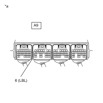
*a Component with harness connected
(Skid Control ECU Assembly)
Reconnect the A9 skid control ECU assembly connector.
-
Reconnect the A17 brake fluid level warning switch (brake master cylinder reservoir assembly) connector.
-
Turn the engine switch on (IG).
-
Measure the voltage according to the value(s) in the table below.
Standard Voltage Tester Connection Condition Specified Condition A9-6 (LBL) - Body ground Brake fluid level warning switch (Brake master cylinder reservoir assembly) off → on 4 to 8 V → Below 1.5 V Result Proceed to OK NG
NG
REPLACE SKID CONTROL ECU ASSEMBLY for RHD: Click here
REPLACE SKID CONTROL ECU ASSEMBLY for LHD: Click hereOK
-
-
RECONFIRM DTC
-
Clear the DTCs.
Chassis > ABS/VSC/TRC > Clear DTCs -
Turn the engine switch off.
-
Turn the engine switch on (IG).
-
Check if the same DTC is output.
Chassis > ABS/VSC/TRC > Trouble CodesResult Result Proceed to DTC C1202/68 is not output. A DTC C1202/68 is output. B
A
USE SIMULATION METHOD TO CHECK Click here
B
REPLACE SKID CONTROL ECU ASSEMBLY for RHD: Click here
REPLACE SKID CONTROL ECU ASSEMBLY for LHD: Click here -