REAR UPPER ARM INSTALLATION

CAUTION / NOTICE / HINT
Tech Tips
-
Use the same procedure for the RH side and LH side.
-
The procedure listed below is for the LH side.
PROCEDURE
-
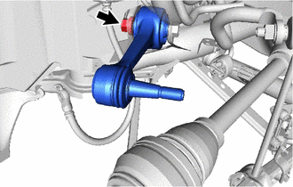
TEMPORARILY TIGHTEN REAR UPPER CONTROL ARM ASSEMBLY LH
-
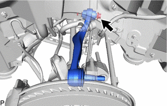
Insert the bolt from the back of the vehicle. Then temporarily tighten the rear upper control arm assembly LH with the nut and washer.
-
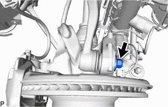
Temporarily tighten the rear upper control arm assembly LH to the rear axle carrier sub-assembly LH with a new nut.
-
-
CONNECT REAR SUSPENSION MEMBER SUB-ASSEMBLY
-
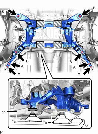
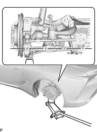
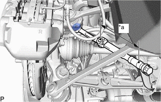
*a Attachment *b Engine Lifter 
Attachment placement location Support the rear suspension member sub-assembly with an engine lifter using 4 attachments or equivalent tools as shown in the illustration.
CAUTION:
-
The rear suspension member sub-assembly is a very heavy component. Make sure that it is supported securely.
-
If the rear suspension member sub-assembly is not securely supported, it may drop, resulting in serious injury.
Note
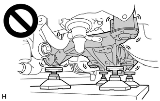
Use attachments to keep the rear suspension member sub-assembly level.
-
-
Raise the rear suspension member sub-assembly until there is no clearance between the rear suspension member sub-assembly and vehicle body.
Note
When raising the rear suspension member sub-assembly, be careful not to damage the vehicle body or other components installed to the vehicle.
-
Install the rear lower suspension member stopper LH, rear lower suspension member stopper RH, 2 rear lower suspension member stoppers and rear suspension member sub-assembly with the 8 bolts.
- Torque:
- Bolt A
- 19 N*m { 194 kgf*cm, 14 ft.*lbf }
- Bolt B
- 135 N*m { 1377 kgf*cm, 100 ft.*lbf }
-
-
INSTALL PROPELLER SHAFT ASSEMBLY
-
INSTALL REAR SHOCK ABSORBER WITH COIL SPRING LH
-
INSTALL REAR SHOCK ABSORBER WITH COIL SPRING RH
Tech Tips
Perform the same procedure as for the LH side.
-
TEMPORARILY TIGHTEN REAR NO. 1 SUSPENSION ARM ASSEMBLY LH
-
Insert the bolt from the back of the vehicle. Then temporarily tighten the rear No. 1 suspension arm assembly LH with the nut and washer.
-
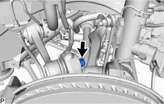
Temporarily tighten the rear No. 1 suspension arm assembly LH to the rear axle carrier sub-assembly LH with a new nut.
-
-
STABILIZE SUSPENSION
-
Install the rear wheel.
-
Lower the vehicle and bounce it up and down several times to stabilize the rear suspension.
-
Remove the rear wheel.
-
Jack up the axle carrier with a wooden block between the jack and axle carrier. Apply a load to the rear suspension so that the rear No. 2 suspension arm assembly LH becomes level.
-
-
FULLY TIGHTEN REAR UPPER CONTROL ARM ASSEMBLY LH
-
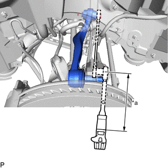
*a Torque Wrench Fulcrum Length Using a ball joint lock nut wrench, fully tighten the rear upper control arm assembly LH with the bolt.
- Torque:
- Specified tightening torque
- 129 N*m { 1315 kgf*cm, 95 ft.*lbf }
Note
Because the nut has its own stopper, do not turn the nut. Tighten the bolt with the nut secured.
Tech Tips
-
Calculate the torque wrench reading when changing the fulcrum length of the torque wrench.
-
When using a ball joint lock nut wrench (fulcrum length of 150 mm (5.906 in.)) + torque wrench (fulcrum length of 400 mm (15.748 in.)): 93.8 N*m (956 kgf*cm, 69 ft.*lbf)
-
Fully tighten the nut.
- Torque:
- 160 N*m { 1632 kgf*cm, 1416 in.*lbf }
-
-
FULLY TIGHTEN REAR NO. 1 SUSPENSION ARM ASSEMBLY LH
-
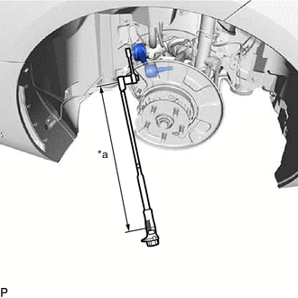
*a Torque Wrench Fulcrum Length Using a ball joint lock nut wrench, fully tighten the rear upper control arm assembly LH with the bolt.
- Torque:
- Specified tightening torque
- 204 N*m { 2080 kgf*cm, 150 ft.*lbf }
Tech Tips
-
Calculate the torque wrench reading when changing the fulcrum length of the torque wrench.
-
When using a ball joint lock nut wrench (fulcrum length of 149.75 mm (5.896 in.)) + torque wrench (fulcrum length of 600 mm (23.622 in.)): 163.3 N*m (1665 kgf*cm, 120 ft.*lbf)
-
*a Torque Wrench Fulcrum Length Using a ball joint lock nut wrench, fully tighten the nut.
- Torque:
- Specified tightening torque
- 160 N*m { 1632 kgf*cm, 118 ft.*lbf }
Tech Tips
-
Calculate the torque wrench reading when changing the fulcrum length of the torque wrench.
-
When using a ball joint lock nut wrench (fulcrum length of 150 mm (5.906 in.)) + torque wrench (fulcrum length of 600 mm (23.622 in.)): 128 N*m (1305 kgf*cm, 94 ft.*lbf)
-
-
INSTALL REAR WHEEL
-
INSPECT AND ADJUST REAR WHEEL ALIGNMENT
-
ADJUST HEADLIGHT AIMING
-
ADJUST REAR TELEVISION CAMERA ASSEMBLY OPTICAL AXIS
-
PERFORM DYNAMIC REAR STEERING SYSTEM CALIBRATION (w/ Dynamic Rear Steering)