FRONT UPPER SUSPENSION ARM INSTALLATION

CAUTION / NOTICE / HINT
Tech Tips
-
Use the same procedure for the RH side and LH side.
-
The procedure listed below is for the LH side.
PROCEDURE
-
INSTALL FRONT UPPER NO. 1 SUSPENSION ARM ASSEMBLY LH
-
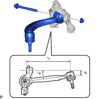
*a 7.25° *b 26.3 mm (1.04 in.) *c 225.6 mm (8.88 in.) Temporarily install the front upper No. 1 suspension arm assembly LH to the front upper No. 1 arm bracket LH with the bolt and nut.
Tech Tips
When installing the front upper No. 1 suspension arm assembly LH, temporarily tighten the bolts at the position shown in the illustration.
-
Fully tighten the bolt.
- Torque:
- 45 N*m { 459 kgf*cm, 33 ft.*lbf }
-
-
INSTALL FRONT UPPER NO. 2 SUSPENSION ARM ASSEMBLY LH
-
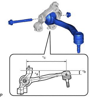
*a 9.15° *b 21 mm (0.827 in.) *c 209.3 mm (8.24 in.) Temporarily install the front upper No. 2 suspension arm assembly LH to the front upper No. 2 arm bracket LH with the bolt and nut.
Tech Tips
When installing the front upper No. 2 suspension arm assembly LH, temporarily tighten the bolts at the position shown in the illustration.
-
Fully tighten the bolt.
- Torque:
- 45 N*m { 459 kgf*cm, 33 ft.*lbf }
-
-
INSTALL FRONT UPPER NO. 1 ARM BRACKET LH
-
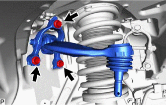
Install the front upper No. 1 arm bracket LH with the 3 bolts.
- Torque:
- 40 N*m { 408 kgf*cm, 30 ft.*lbf }
-
-
INSTALL FRONT UPPER NO. 2 ARM BRACKET LH
-
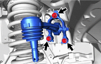
Install the front upper No. 2 arm bracket LH with the 3 bolts.
- Torque:
- 40 N*m { 408 kgf*cm, 30 ft.*lbf }
-
-
CONNECT STEERING KNUCKLE ASSEMBLY LH
-
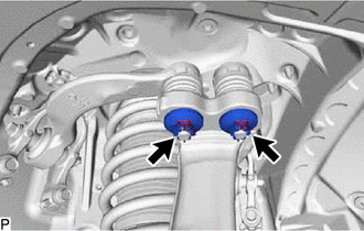
Install the steering knuckle assembly LH to the front upper No. 1 suspension arm assembly LH and front upper No. 2 suspension arm assembly LH with the 2 nuts.
- Torque:
- 60 N*m { 612 kgf*cm, 44 ft.*lbf }
-
Install 2 new clips.
Note
Further tighten the nut up to 60° if the holes for the clip are not aligned.
-
-
INSTALL FRONT WHEEL
-
INSPECT AND ADJUST FRONT WHEEL ALIGNMENT
-
ADJUST HEADLIGHT AIMING