FRONT WHEEL ALIGNMENT ADJUSTMENT
CAUTION / NOTICE / HINT
The necessary procedures (adjustment, calibration, initialization, or registration) that must be performed after completing the front wheel alignment procedure are shown below.
| Replacement Part or Procedure | Necessary Procedures | Effects/Inoperative when not Performed | Link |
|---|---|---|---|
| Parts between the steering wheel and tires have been removed/installed, replaced or adjusted | Perform Actuator Angle Neutral Point Calibration and Initialization |
|
|
| Suspension, tires, etc*1 | Television camera assembly optical axis (Back camera position setting) | Parking assist monitor system |
*1: The vehicle height changes due to suspension or tire replacement.
PROCEDURE
-
INSPECT TIRES
-
MEASURE VEHICLE HEIGHT
Note
-
Before inspecting the wheel alignment, adjust the vehicle height to the specified value.
-
Be sure to perform measurement on a level surface.
-
If it is necessary to go under the vehicle for measurement, confirm that the parking brake is applied and the vehicle is secured with chocks.
-
Inspect while the vehicle is unloaded.
-
The standard value shown here is a value that is used for performing a wheel alignment and does not indicate the height of an actual vehicle.
-
Bounce the vehicle up and down at the corners to stabilize the suspension.
-
Measure the vehicle height.
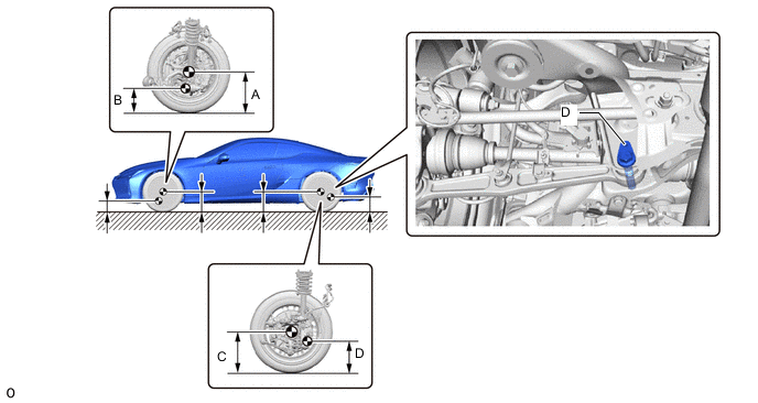
-
A: Ground clearance of front wheel center
Measurement Points:
-
B: Ground clearance of front center position of front No. 2 suspension lower arm assembly front bush installation bolt
-
C: Ground clearance of rear wheel center
-
D: Ground clearance of pin hole center of the rear suspension arm attachment sub-assembly
Vehicle Height (Unloaded Vehicle) Front A - B Rear C - D 137.0 mm (5.39 in.) 88.0 mm (3.46 in.) -
-
-
INSPECT CAMBER, CASTER AND STEERING AXIS INCLINATION
Note
Inspect while the vehicle is unloaded.
-
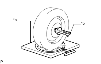
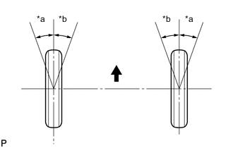
*a Turning Radius Gauge *b Camber-caster-kingpin Gauge Install a camber-caster-kingpin gauge and place the front wheels on the center of a turning radius gauge.
-
Inspect the camber, caster and steering axis inclination.
Camber (Unloaded Vehicle) Camber Inclination Right-left Difference 0°42' +/- 0°45' (0.70° +/-0.75°) 0°45' (0.75°) or less Caster (Unloaded Vehicle) Caster Inclination Right-left Difference 7°25' +/- 0°45' (7.42° +/-0.75°) 0°45' (0.75°) or less Steering Axis Inclination (Unloaded Vehicle) Steering Axis Inclination Reference 8°56' (8.93°)
-
-
INSPECT TOE-IN
Note
Inspect while the vehicle is unloaded.
-
Bounce the vehicle up and down at the corners to stabilize the suspension.
-
Release the parking brake and move the shift lever to N.
-
Push the vehicle straight ahead approximately 5 m (16.4 ft.). (Step C)
-
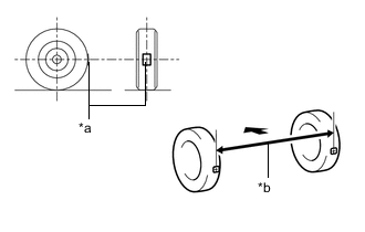
*a Tread Center Mark *b Dimension B 
Front of the Vehicle Put tread center marks on the rearmost points of the front wheels and measure the distance between the marks (dimension B).
-
Slowly push the vehicle straight ahead to cause the front wheels to rotate 180°. Use the front tire valve as a reference point.
Tech Tips
Do not allow the wheels to rotate more than 180°. If the wheels rotate more than 180°, perform the procedure from step C again.
-
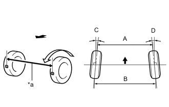
*a Dimension A Front of the Vehicle Measure the distance between the tread center marks on the front of the wheels (dimension A).
Toe-in (Unloaded Vehicle) Specified Condition C + D: 0°00' +/- 0°09' (0.00° +/-0.15°) B - A: 0.0 +/- 2.0 mm (0 +/- 0.0787 in.) Tech Tips
Measure "B - A" only when "C + D" cannot be measured.
If the toe-in is not within the specified range, adjust it at the steering rack ends.
-
-
ADJUST TOE-IN
-
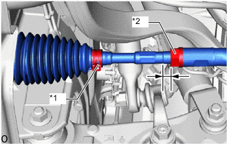
*1 Steering Rack Boot Clip *2 Lock Nut Make sure that the thread length of the right and left steering rack ends are approximately the same.
Standard Difference 1.5 mm (0.0591 in.) or less -
Remove the steering rack boot clips.
-
Loosen the tie rod assembly lock nuts.
-
Adjust the steering rack ends if the difference in thread length between the right and left steering rack ends is not within the specified range.
-
If the toe-in measurement is greater than the specified range (too much toe-in), lengthen the shorter steering rack end so that the length difference is within the specified range.
-
If the toe-in measurement is less than the specified range (too much toe-out), shorten the longer steering rack end so that the length difference is within the specified range.
-
Measure the toe-in.
-
-
Turn the right and left steering rack ends by an equal amount to adjust the toe-in.
Toe-in (Unloaded Vehicle) Specified Condition C + D: 0°00' +/- 0°09' (0.00° +/-0.15°) B - A: 0.0 +/- 2.0 mm (0 +/- 0.0787 in.) Tech Tips
Perform adjustments so that the value is as close as possible to the median of the specified range.
-
Make sure that the thread length of the right and left steering rack ends are the same.
-
Tighten the tie rod assembly lock nuts.
- Torque:
- 88 N*m { 897 kgf*cm, 65 ft.*lbf }
-
Place the steering rack boots on the seats and install the steering rack boot clips.
Tech Tips
-
Make sure that the steering rack boots are not twisted.
-
Make sure that the steering rack boot clips are facing towards the front of the vehicle.
-
-
-
INSPECT WHEEL ANGLE
-
*a Inside *b Outside Front of the Vehicle Put tread center marks on the rearmost points of a turning radius gauge.
-
Turn the steering wheel fully to the left and right and measure the turning angle.
Note
Inspect while the vehicle is unloaded.
Wheel Turning Angle (Unloaded Vehicle) Inside Wheel Outside Wheel 39°07' +/- 2°00' (39.12° +/- 2°00' ) 33°50' (33.83°)
-
If the right and left inside wheel angles differ from the specified value, check and adjust the right and left steering rack end lengths.
-
-
-
INSPECT FRONT SUSPENSION
-
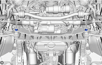
Inspect the front frame crossmember sub-assembly.
-
Measure the dimension between the center of the 2 installation bolts of the front lower suspension arm assembly.
Standard 775.2 mm (2.54 ft.) If the result is not within the specification, replace the front frame crossmember sub-assembly.
-
-
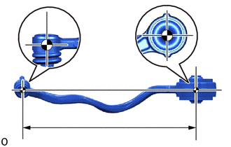
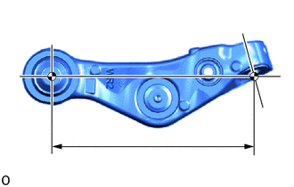
Inspect the front lower suspension arm assembly.
-
Remove the front lower suspension arm assembly.
-
Measure the dimension between the center of the front lower suspension arm assembly bush and the ball joint stud.
Standard 493.6 +/- 0.46 mm (19.4330 +/- 0.0181 in.)
-
-
Inspect the lower No. 2 suspension arm assembly.
-
Remove the lower No. 2 suspension arm assembly.
-
Measure the dimension between the center of the lower No. 2 suspension arm assembly bush and the center of the ball joint.
Standard 309.9 +/- 0.4 mm (12.2008 +/- 0.0157 in.)
-
-
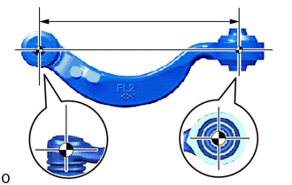
Inspect the front upper No. 1 suspension arm assembly.
-
Remove the front upper No. 1 suspension arm assembly.
-
Measure the dimension between the center of the front upper No. 1 suspension arm assembly bush and the ball joint stud.
Standard 232.6 +/- 0.46 mm (9.1575 +/- 0.0181 in.)
-
-
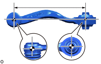
Inspect the front upper No. 2 suspension arm assembly.
-
Remove the front upper No. 2 suspension arm assembly.
-
Measure the dimension between the center of the front upper No. 2 suspension arm assembly bush and the center of the ball joint stud.
Standard 218.5 +/- 0.46 mm (8.6023 +/- 0.0181 in.)
-
-
-
ALIGN FRONT WHEELS FACING STRAIGHT AHEAD
-
PERFORM YAW RATE AND ACCELERATION SENSOR CALIBRATION