ADAPTIVE VARIABLE SUSPENSION SYSTEM, Diagnostic DTC:C1715, C1716, C1717, C1796, C1797, C1798
| DTC Code | DTC Name |
|---|---|
| C1715 | Front Acceleration Sensor RH Malfunction |
| C1716 | Front Acceleration Sensor LH Malfunction |
| C1717 | Rear Acceleration Sensor Malfunction |
| C1796 | Front Acceleration Sensor RH Malfunction (Test Mode DTC) |
| C1797 | Front Acceleration Sensor LH Malfunction (Test Mode DTC) |
| C1798 | Rear Acceleration Sensor Malfunction (Test Mode DTC) |
DESCRIPTION
The acceleration sensor (up and down G sensor) detects the upward and downward acceleration of the vehicle and outputs it as a voltage to the absorber control ECU.
The 3 up and down G sensors are installed in the driver side instrument panel, the passenger sideinstrument panel and the absorber control ECU.
Each up and down G sensor independently detects the upward and downward acceleration of the vehicle.
During a test mode inspection, the absorber control ECU reads the fluctuations in each sensor signal.
When a sensor signal does not fluctuate, test mode DTCs C1796, C1797 and C1798 remain stored.
| DTC No. | Detection Item | DTC Detection Condition | Trouble Area | Warning Indicate | Memory |
|---|---|---|---|---|---|
| C1715 | Front Acceleration Sensor RH Malfunction | One of the following conditions is met:
|
|
Does not come on | Yes |
| C1716 | Front Acceleration Sensor LH Malfunction | One of the following conditions is met:
|
|
Does not come on | Yes |
| C1717 | Rear Acceleration Sensor Malfunction | One of the following conditions is met:
|
Absorber control ECU | Does not come on | Yes |
| C1796 | Front Acceleration Sensor RH Malfunction (Test Mode DTC) | With the vehicle stationary on a level surface, an acceleration sensor value that is within -1.96 to 1.96 m/s2is not received from the front acceleration sensor RH for 1 second or more. |
|
Test mode | Test mode |
| C1797 | Front Acceleration Sensor LH Malfunction (Test Mode DTC) | With the vehicle stationary on a level surface, an acceleration sensor value that is within -1.96 to 1.96 m/s2is not received from the front acceleration sensor LH for 1 second or more. |
|
Test mode | Test mode |
| C1798 | Rear Acceleration Sensor Malfunction (Test Mode DTC) | With the vehicle stationary on a level surface, an acceleration sensor value that is within -1.96 to 1.96 m/s2is not received from the rear acceleration sensor (absorber control ECU) for 1 second or more. |
Absorber control ECU | Test mode | Test mode |
WIRING DIAGRAM
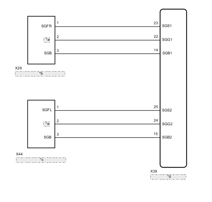
| *a | SGG |
| *b | Front Acceleration Sensor RH |
| *c | Front Acceleration Sensor LH |
| *d | Absorber Control ECU |
CAUTION / NOTICE / HINT
Note
-
Before performing troubleshooting, inspect the connectors of related circuits.
-
If DTC C1782 (Power Source Voltage Malfunction) is output at the same time, perform troubleshooting for C1782 first.
-
Before replacing the absorber control ECU, perform all of the following:
-
Symptom simulation.
-
DTC inspection.
-
GTS inspection.
-
If no malfunctions are found in other areas, replace the absorber control ECU.
-
After replacing the absorber control ECU with a new one, perform registration of vehicle identification information.
PROCEDURE
-
READ VALUE USING GTS ((UP & DOWN) G SENSOR)
-
Turn the engine switch off.
-
Connect the GTS to the DLC3.
-
Turn the engine switch on (IG).
-
Turn the GTS on.
-
Enter the following menus: Chassis / Air suspension / Data List.
Chassis > Air suspension > Data ListTester Display Measurement Item Range Normal Condition Diagnostic Note (Up&Down)G Sensor FR Front acceleration sensor RH (up and down) Min.: -1045.29 m/s2
Max.: 1045.26 m/s2
-0.98 to 0.98 m/s2
when stationary
The value changes when the vehicle (front RH) is bounced. (Up&Down)G Sensor FL Front acceleration sensor LH (up and down) Min.: -1045.29 m/s2
Max.: 1045.26 m/s2
-0.98 to 0.98 m/s2
when stationary
The value changes when the vehicle (front LH) is bounced. (Up&Down)G Sensor Rear Rear acceleration sensor (up and down) Min.: -1045.29 m/s2
Max.: 1045.26 m/s2
-0.98 to 0.98 m/s2
when stationary
The value changes when the vehicle (rear) is bounced.
Chassis > Air suspension > Data ListTester Display (Up&Down)G Sensor FR (Up&Down)G Sensor FL (Up&Down)G Sensor Rear OK The values are as specified in the normal condition column. Result Result Proceed to OK A NG (front RH or front LH) B NG (rear) C
B 
GO TO STEP 3 Click here
C 
REPLACE ABSORBER CONTROL ECU Click here
A 
-
-
CHECK FOR DTCS
-
Clear the DTCs.
Chassis > Air suspension > Clear DTCs -
Turn the engine switch off.
-
Check for DTCs.
Chassis > Air suspension > Trouble CodesResult Result Proceed to DTCs are output (front RH or front LH) A DTCs are output (rear) B DTCs are not output C
B
REPLACE ABSORBER CONTROL ECU Click here
C
USE SIMULATION METHOD TO CHECK Click here
A
-
-
INSPECT FRONT ACCELERATION SENSOR
-
Turn the engine switch off.
-
Remove the front acceleration sensor RH or front acceleration sensor LH.
-
Inspect the front acceleration sensor RH or front acceleration sensor LH.
Result Result Proceed to OK A Front acceleration sensor RH malfunction B Front acceleration sensor LH malfunction C
B
REPLACE FRONT ACCELERATION SENSOR RH Click here
C
REPLACE FRONT ACCELERATION SENSOR LH Click here
A
-
-
CHECK HARNESS AND CONNECTOR (FRONT ACCELERATION SENSOR - ABSORBER CONTROL ECU)
-
Check the front acceleration sensor RH harness and connector (when DTC C1715 is output).
-
Disconnect the X39 absorber control ECU connector.
-
Disconnect the X29 front acceleration sensor RH connector.
-
Measure the resistance according to the value(s) in the table below.
Standard Resistance Tester Connection Condition Specified Condition X29-1 (SGFR) - X39-23 (SGS1) Always Below 1 Ω X29-2 (SGG) - X39-22 (SGG1) Always Below 1 Ω X29-3 (SGB) - X39-14 (SGB1) Always Below 1 Ω X29-1 (SGFR) or X39-23 (SGS1) - Body ground Always 10 kΩ or higher X29-2 (SGG) or X39-22 (SGG1) - Body ground Always 10 kΩ or higher X29-3 (SGB) or X39-14 (SGB1) - Body ground Always 10 kΩ or higher
-
-
Check the front acceleration sensor LH harness and connector (when DTC C1716 is output).
-
Disconnect the X39 absorber control ECU connector.
-
Disconnect the X44 front acceleration sensor LH connector.
-
Measure the resistance according to the value(s) in the table below.
Standard Resistance Tester Connection Condition Specified Condition X44-1 (SGFL) - X39-25 (SGS2) Always Below 1 Ω X44-2 (SGG) - X39-24 (SGG2) Always Below 1 Ω X44-3 (SGB) - X39-15 (SGB2) Always Below 1 Ω X44-1 (SGFL) or X39-25 (SGS2) - Body ground Always 10 kΩ or higher X44-2 (SGG) or X39-24 (SGG2) - Body ground Always 10 kΩ or higher X44-3 (SGB) or X39-15 (SGB2) - Body ground Always 10 kΩ or higher
Result Proceed to OK NG -
OK
REPLACE ABSORBER CONTROL ECU Click here
NG
REPAIR OR REPLACE HARNESS OR CONNECTOR
-