AUTOMATIC TRANSMISSION UNIT REASSEMBLY

PROCEDURE
-
BEARING POSITION
-
Check each bearing position and installation direction.
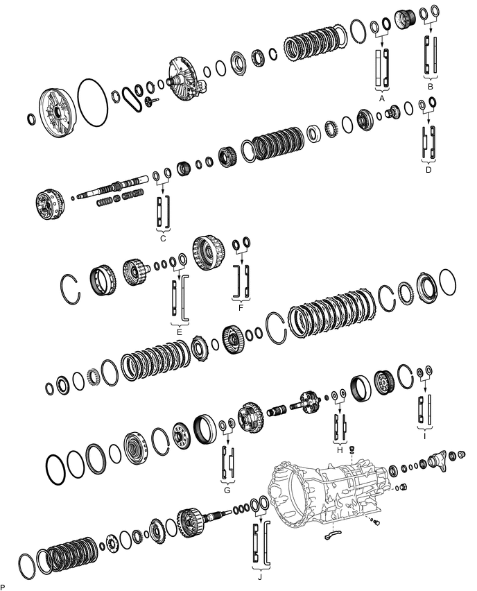
Bearing Position Position Front Race Diameter
Inside/Outside
Thrust Bearing Diameter
Inside/Outside
Rear Race Diameter
Inside/Outside
(A) 56.63 mm (2.230 in.) / 73.00 mm (2.874 in.) 57.40 mm (2.260 in.) / 75.00 mm (2.953 in.) - (B) - 56.00 mm (2.205 in.) / 73.70 mm (2.902 in.) 52.50 mm (2.067 in.) / 71.70 mm (2.823 in.) (C) - 37.70 mm (1.484 in.) / 56.30 mm (2.217 in.) 40.90 mm (1.610 in.) / 60.40 mm (2.378 in.) (D) 40.30 mm (1.587 in.) / 58.20 mm (2.291 in.) 43.00 mm (1.693 in.) / 60.00 mm (2.362 in.) - (E) - 47.60 mm (1.874 in.) / 63.80 mm (2.512 in.) 48.60 mm (1.913 in.) / 73.10 mm (2.878 in.) (F) 42.50 mm (1.673 in.) / 58.30 mm (2.295 in.) 43.00 mm (1.693 in.) / 60.00 mm (2.362 in.) - (G) - 50.00 mm (1.969 in.) / 70.00 mm (2.756 in.) 47.40 mm (1.866 in.) / 66.40 mm (2.614 in.) (H) - 22.70 mm (0.894 in.) / 48.40 mm (1.906 in.) 23.30 mm (0.917 in.) / 48.40 mm (1.906 in.) (I) 30.00 mm (1.181 in.) / 49.00 mm (1.929 in.) 32.60 mm (1.283 in.) / 54.20 mm (2.134 in.) (J) - 58.90 mm (2.319 in.) / 76.65 mm (3.018 in.) 62.00 mm (2.441 in.) / 82.50 mm (3.248 in.)
-
-
INSTALL AUTOMATIC TRANSMISSION CASE PLUG
Tech Tips
If automatic transmission fluid leaks from a automatic transmission case plug or the plug is corroded, replace it.
-
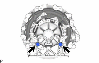
for T55 "TORX":
-
Using a T55 "TORX" socket wrench, install the 2 automatic transmission case plugs and 2 new O-rings to the automatic transmission case.
- Torque:
- 39.2 N*m { 400 kgf*cm, 29 ft.*lbf }
-
-
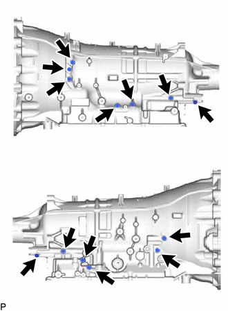
for 12 mm head:
-
Install the 13 automatic transmission case plugs and 13 new O-rings to the automatic transmission case.
- Torque:
- 7.35 N*m { 75 kgf*cm, 65 in.*lbf }
-
-
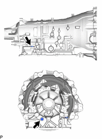
for 24 mm head:
-
Install the 2 automatic transmission case plugs and 2 new O-rings to the automatic transmission case.
- Torque:
- 39.2 N*m { 400 kgf*cm, 29 ft.*lbf }
-
-
-
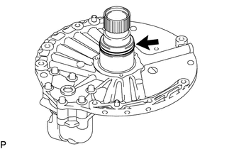
INSTALL OUTPUT SHAFT REAR RADIAL BALL BEARING
-
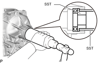
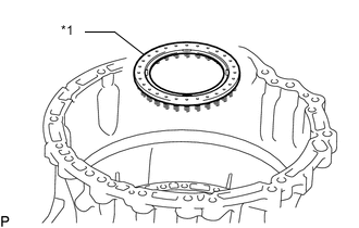
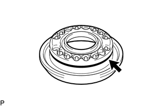
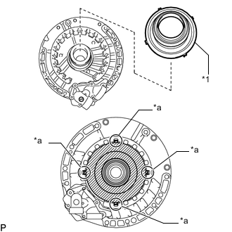
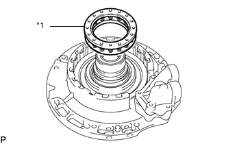
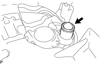
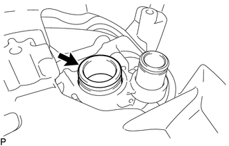
Using SST, install a new output shaft rear radial ball bearing to the automatic transmission case.
- SST
- 09316-60011 ( 09316-00011, 09316-00021 )
-
-
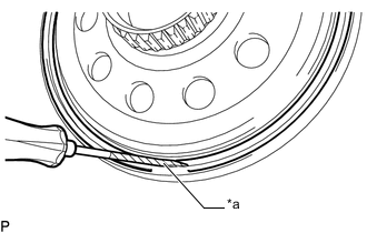
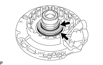
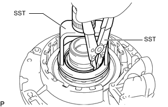
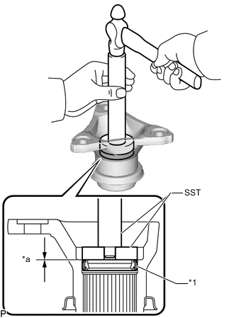
INSTALL FLANGE YOKE TYPE T OIL SEAL
-
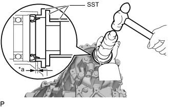
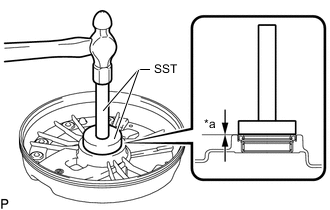
*a 3.2 to 3.8 mm (0.126 to 0.150 in.) Using SST and a hammer, install a new flange yoke type T oil seal to the automatic transmission case.
- SST
- 09316-60011 ( 09316-00011, 09316-00041 )
- 09502-12010
Flange Yoke Type T Oil Seal Installation Depth 3.2 to 3.8 mm (0.126 to 0.150 in.) Note
-
Keep the flange yoke type T oil seal lip free of foreign matter.
-
Do not install the flange yoke type T oil seal at an angle.
-
When installing the flange yoke type T oil seal to the automatic transmission case, do not damage the flange yoke type T oil seal.
-
Coat the lip of the flange yoke type T oil seal with MP grease.
-
-
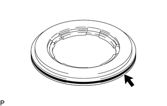
INSTALL BRAKE PLATE STOPPER SPRING
-
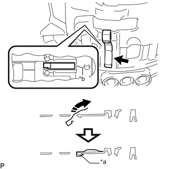
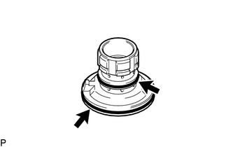
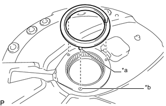
*a Securely install the case stopper *b Groove of automatic transmission case 
Install in the direction of the arrow Install the brake plate stopper spring to the automatic transmission case as shown in the illustration.
Note
Install the brake plate stopper spring to the groove in the automatic transmission case and push until it is secured to the automatic transmission case stopper.
-
-
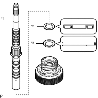
INSTALL C-4 CLUTCH PISTON
-
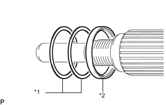
Coat the 3 new clutch drum oil seal rings with ATF and install it to the output shaft assembly.
-
Coat a new O-ring with ATF and install it to the output shaft assembly.
-
Coat a new O-ring with ATF and install it to the C-4 clutch piston.
-
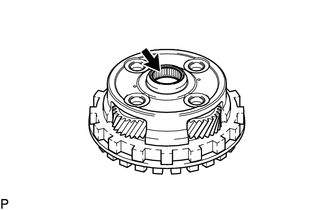
*1 C-4 Clutch Piston Install the C-4 clutch piston to the output shaft assembly.
-
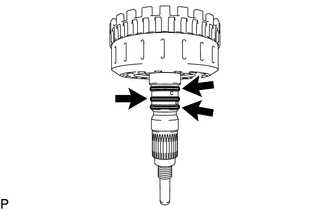
Coat a new O-ring with ATF and install it to the C-4 clutch balancer.
-
*1 C-4 Clutch Balancer *2 Direct Clutch Return Spring Sub-assembly (C-4 clutch) Install the C-4 clutch balancer and direct clutch return spring sub-assembly (C-4 clutch) to the output shaft assembly.
-
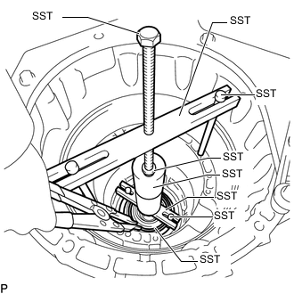
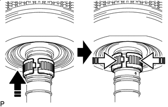
Set SST on the C-4 clutch balancer and compress the direct clutch return spring sub-assembly (C-4 clutch) using a press.
- SST
- 09387-00020
Note
Stop the press when the C-4 clutch balancer is lowered to a place 1 to 2 mm (0.0394 to 0.0787 in.) below the snap ring groove to prevent the direct clutch return spring sub-assembly (C-4 clutch) from being deformed.
-
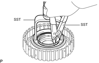
Using SST, install the snap ring to the output shaft assembly.
- SST
- 09350-30020 ( 09350-07070 )
Note
-
Make sure that the end gap of the snap ring is not aligned with a spring retainer claw.
-
Do not expand the snap ring excessively.
-
-
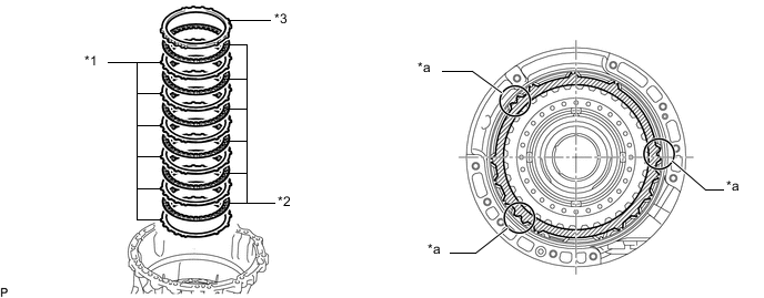
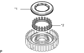
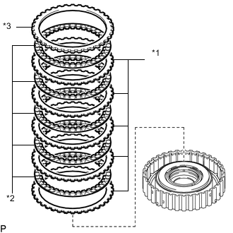
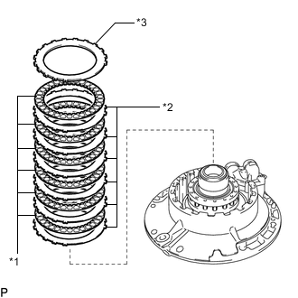
INSTALL NO. 4 CLUTCH DISC
-
*1 No. 4 Clutch Plate *2 No. 4 Clutch Disc *3 Clutch Flange Install the 6 No. 4 clutch plates, 6 No. 4 clutch discs and clutch flange to the output shaft assembly.
Note
Make sure that the No. 4 clutch discs, No. 4 clutch plates and clutch flange are installed in the correct order.
-
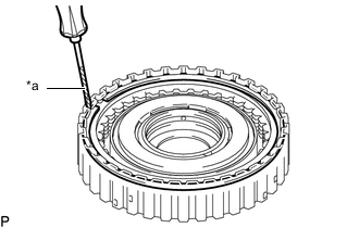
*a Protective Tape Using a screwdriver, install the snap ring to the output shaft assembly.
Note
Be careful not to damage the output shaft assembly.
Tech Tips
Tape the screwdriver tip before use.
-
-
INSPECT PISTON STROKE OF NO. 4 CLUTCH
-
INSTALL OUTPUT SHAFT ASSEMBLY WITH C-4 CLUTCH
-
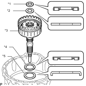
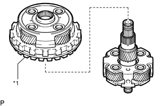
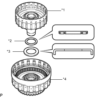
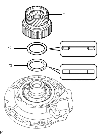
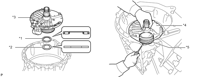
*1 Thrust Needle Roller Bearing (I) *2 Thrust Bearing Race (I) *3 Output Shaft Assembly with C-4 Clutch *4 Thrust Needle Roller Bearing (J) *5 Thrust Bearing Race (J) Install the output shaft assembly with C-4 clutch, 2 thrust needle roller bearings and 2 thrust bearing races.
Thrust Needle Roller Bearing and Thrust Bearing Race Diameter Item Inside Outside Thrust needle roller bearing (I) 30.00 mm (1.181 in.) 49.00 mm (1.929 in.) Thrust bearing race (I) 32.60 mm (1.283 in.) 54.20 mm (2.134 in.) Thrust needle roller bearing (J) 58.90 mm (2.319 in.) 76.65 mm (3.018 in.) Thrust bearing race (J) 62.00 mm (2.441 in.) 82.50 mm (3.248 in.)
-
-
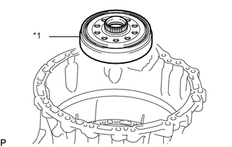
INSTALL REAR PLANETARY RING GEAR FLANGE SUB-ASSEMBLY
-
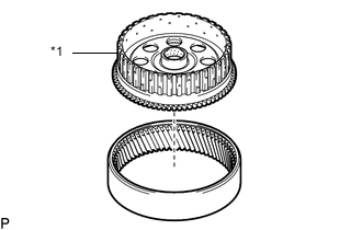
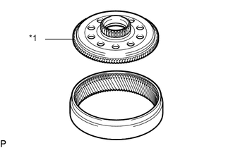
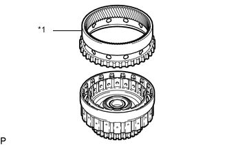
*1 Rear Planetary Ring Gear Flange Sub-assembly Install the rear planetary ring gear flange sub-assembly to the rear planetary ring gear.
-
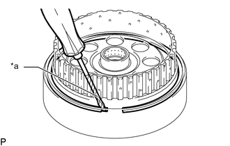
*a Protective Tape Using a screwdriver, install the snap ring to the rear planetary ring gear.
Note
Be careful not to damage the rear planetary ring gear.
Tech Tips
Tape the screwdriver tip before use.
-
-
INSTALL REAR PLANETARY RING GEAR WITH REAR PLANETARY RING GEAR FLANGE SUB-ASSEMBLY
-
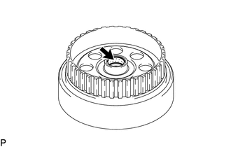
Coat the ATF to the inside of the rear planetary ring gear with rear planetary ring gear flange sub-assembly bushing.
-
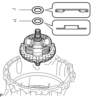
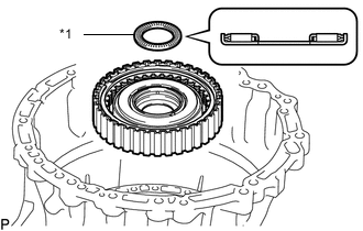
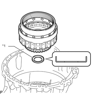
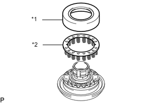
*1 Thrust Needle Roller Bearing (H) *2 Thrust Bearing Race (H) Install the rear planetary ring gear with rear planetary ring gear flange sub-assembly, thrust needle roller bearing and thrust bearing race.
Thrust Needle Roller Bearing and Thrust Bearing Race Diameter Item Inside Outside Thrust needle roller bearing (H) 22.70 mm (0.894 in.) 48.40 mm (1.906 in.) Thrust bearing race (H) 23.30 mm (0.917 in.) 48.40 mm (1.906 in.)
-
-
INSTALL PLANETARY SUN GEAR SUB-ASSEMBLY
-
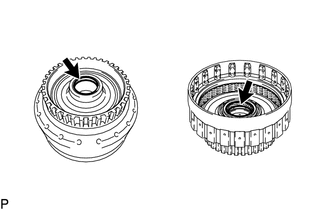
Coat a new oil seal ring with ATF and install it to the rear planetary gear assembly.
-
Coat the ATF to the inside of the planetary sun gear sub-assembly bushing.
-
*1 Planetary Sun Gear Sub-assembly Install the planetary sun gear sub-assembly to the rear planetary gear assembly.
Note
Check that the planetary sun gear sub-assembly rotates smoothly.
-
-
INSTALL CENTER PLANETARY GEAR ASSEMBLY
-
Coat the ATF to the inside of the center planetary gear assembly bearing.
-
*1 Center Planetary Gear Assembly Install the center planetary gear assembly to the rear planetary gear assembly.
-
-
INSTALL REAR PLANETARY GEAR ASSEMBLY WITH PLANETARY SUN GEAR SUB-ASSEMBLY AND CENTER PLANETARY GEAR ASSEMBLY
-
*1 Thrust Needle Roller Bearing (G) *2 Thrust Bearing Race (G) Install the rear planetary gear assembly with planetary sun gear sub-assembly and center planetary gear assembly, thrust needle roller bearing and thrust bearing race.
Thrust Needle Roller Bearing and Thrust Bearing Race Diameter Item Inside Outside Thrust needle roller bearing (G) 50.00 mm (1.969 in.) 70.00 mm (2.756 in.) Thrust bearing race (G) 47.40 mm (1.866 in.) 66.40 mm (2.614 in.)
-
-
INSTALL CENTER PLANETARY RING GEAR FLANGE
-
*1 Center Planetary Ring Gear Flange Install the center planetary ring gear flange to the center planetary ring gear.
-
*a Protective Tape Using a screwdriver, install the snap ring to the center planetary ring gear.
Note
Be careful not to damage the center planetary ring gear.
Tech Tips
Tape the screwdriver tip before use.
-
-
INSTALL CENTER PLANETARY RING GEAR WITH CENTER PLANETARY RING GEAR FLANGE
-
*1 Center Planetary Ring Gear with Center Planetary Ring Gear Flange Install the center planetary ring gear with center planetary ring gear flange to the rear planetary gear assembly with planetary sun gear sub-assembly and center planetary gear assembly.
-
-
INSTALL 1ST AND REVERSE BRAKE PISTON
-
Coat a new O-ring with ATF and install it to the center support sub-assembly.
-
Coat the 2 new O-rings with ATF and install them to the 1st and reverse brake piston.
-
*1 1st and Reverse Brake Piston Install the 1st and reverse brake piston to the center support sub-assembly.
-
-
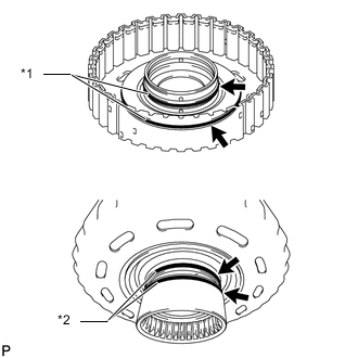
INSTALL NO. 2 BRAKE PISTON
-
Coat a new O-ring with ATF and install it to the No. 2 brake piston.
-
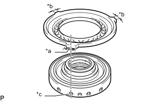
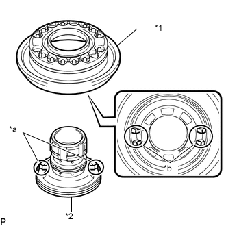
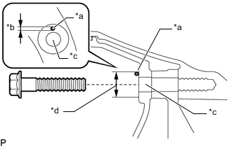
*a Wide Claw Width *b Narrow Claw Width *c Oil Hole Install the No. 2 brake piston to the center support sub-assembly.
Note
Align the claw of the No. 2 brake piston with the oil hole of the center support sub-assembly and install it as shown in the illustration.
-
-
INSTALL CENTER SUPPORT SUB-ASSEMBLY, 1ST AND REVERSE BRAKE PISTON WITH NO. 2 BRAKE PISTON
-
Coat the ATF to the inside of the center support sub-assembly bushing.
-
Install the center support sub-assembly, 1st and reverse brake piston with No. 2 brake piston to the automatic transmission case.
Note
-
Check that the oil holes of the center support sub-assembly and automatic transmission case are aligned.
-
Install the bolt with the center support sub-assembly contacting the surface of the automatic transmission case.
-
Install so that the claw of the No. 2 brake piston is facing the position shown in the illustration.
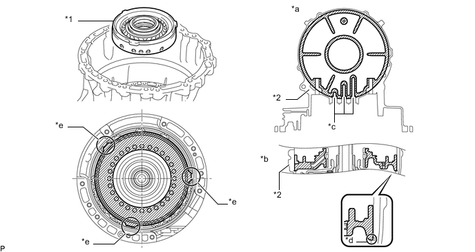
*1 Center Support Sub-assembly, 1st and Reverse Brake Piston with No. 2 Brake Piston *2 Automatic Transmission Case *a Top View *b Cross Sectional View *c Oil Hole *d Automatic Transmission Case Contact Surface *e Claw of No. 2 Brake Piston - - -
-
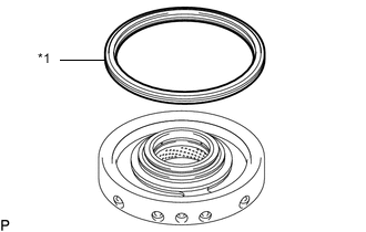
*1 2nd Brake Piston Return Spring Sub-assembly Install the 2nd brake piston return spring sub-assembly to the No. 2 brake piston.
-
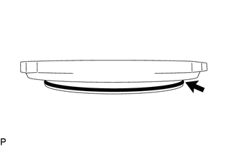
Set SST on the 2nd brake piston return spring sub-assembly, automatic transmission case and tighten SST to compress the 2nd brake piston return spring sub-assembly.
- SST
- 09308-14010
- 09380-60012 ( 09381-06010, 09381-06020, 09381-06040, 09381-06050, 09381-06090, 09381-06120, 09381-06150 )
-
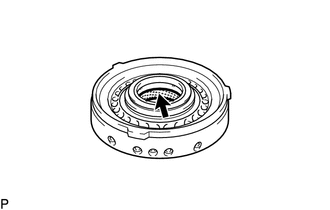
Using snap ring expander, install the hole snap ring to the center support sub-assembly.
-
Install the 2 bolts to the center support sub-assembly with 1st and reverse brake piston.
- Torque:
- 25.45 N*m { 260 kgf*cm, 19 ft.*lbf }
-
-
INSTALL NO. 2 BRAKE DISC
-
Install the 6 No. 2 brake plates, 6 No. 2 brake discs and No. 2 brake flange to the automatic transmission case.
Note
-
Install so that the equal width claws of the No. 2 brake plate and No. 2 brake flange are facing the position shown in the illustration.
-
Make sure that the No. 2 brake discs and No. 2 brake plates, No. 2 brake flange are installed in the correct order.
Tech Tips
Align the protrusions of the No. 2 brake flange and No. 2 brake plates with the cutouts of the automatic transmission case.
*1 No. 2 Brake Plate *2 No. 2 Brake Disc *3 No. 2 Brake Flange - - *a Equal width claws of the No. 2 brake plate and No. 2 brake flange - - -
-
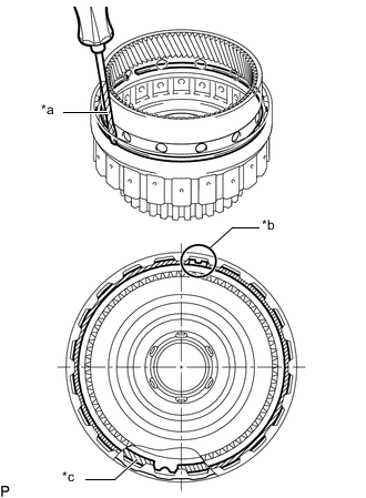
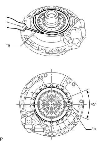
Using a screwdriver, install the snap ring to the automatic transmission case.
Note
-
The snap ring end gap position must be within the 45° range shown in the illustration.
-
Be careful not to damage the automatic transmission case.
Tech Tips
Tape the screwdriver tip before use.
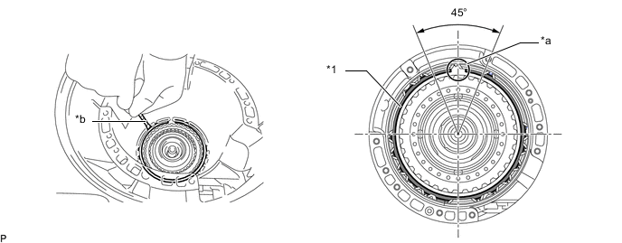
*1 Snap Ring - - *a Snap ring end gap position *b Protective Tape -
-
-
INSPECT PISTON STROKE OF NO. 2 BRAKE
-
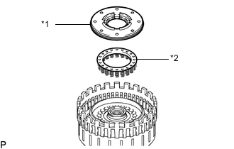
INSTALL C-3 CLUTCH PISTON
-
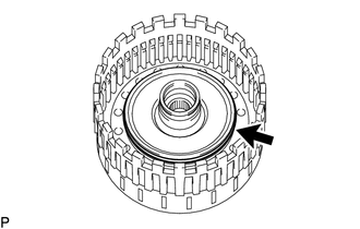
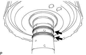
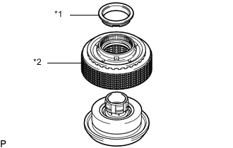
*1 O-ring *2 Oil Seal Ring Coat the 2 new O-rings with ATF and install it to the C-3 drum sub-assembly.
-
Coat the 2 new oil seal rings with ATF and install it to the C-3 drum sub-assembly.
-
*1 C-3 Clutch Piston Install the C-3 clutch piston to the C-3 drum sub-assembly.
-
-
INSTALL NO. 3 CLUTCH DISC
-
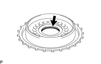
Coat a new O-ring with ATF and install it to the C-3 clutch balancer.
-
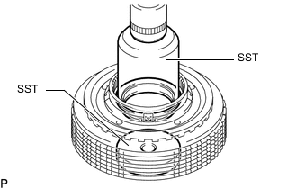
*1 C-3 Clutch Balancer *2 Direct Clutch Return Spring Sub-assembly (C-3 Clutch) Install the C-3 clutch balancer and direct clutch return spring sub-assembly (C-3 clutch) to the C-3 drum sub-assembly.
-
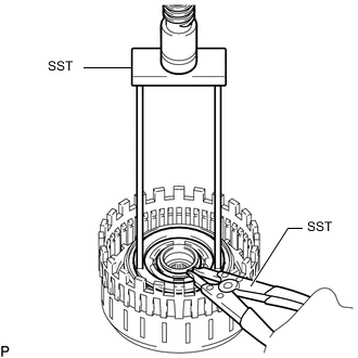
Set SST on the C-3 clutch balancer and compress the direct clutch return spring sub-assembly (C-3 clutch) using a press.
- SST
- 09320-89010
Note
Stop the press when the C-3 clutch balancer is lowered to a place 1 to 2 mm (0.0394 to 0.0787 in.) below the snap ring groove to prevent the direct clutch return spring sub-assembly (C-3 clutch) from being deformed.
-
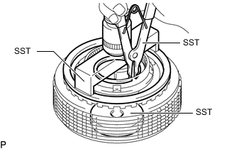
Using SST, install the snap ring to the C-3 drum sub-assembly.
- SST
- 09350-30020 ( 09350-07070 )
-
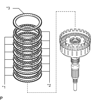
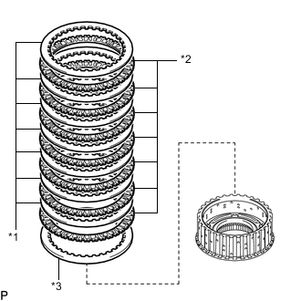
*1 No. 3 Clutch Plate *2 No. 3 Clutch Disc *3 Clutch Flange Install the 5 No. 3 clutch plates, 5 No. 3 clutch discs and clutch flange to the C-3 drum sub-assembly.
Note
Make sure that the No. 3 clutch discs, No. 3 clutch plates and clutch flange are installed in the correct order.
-
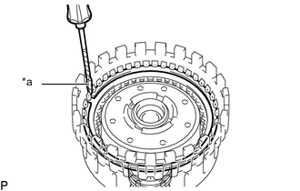
*a Protective Tape Using a screwdriver, install the snap ring to the C-3 drum sub-assembly.
Note
Be careful not to damage the C-3 drum sub-assembly.
Tech Tips
Tape the screwdriver tip before use.
-
-
INSTALL C-3 CLUTCH ASSEMBLY
-
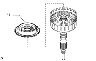
*1 Thrust Needle Roller Bearing (F) Install the C-3 clutch assembly and thrust needle roller bearing.
Thrust Needle Roller Bearing Item Inside Outside Thrust needle roller bearing (F) 43.00 mm (1.693 in.) 60.00 mm (2.362 in.)
-
-
INSPECT PISTON STROKE OF NO. 3 CLUTCH
-
INSPECT PISTON STROKE OF C-1 CLUTCH ASSEMBLY
-
INSTALL C-2 DRUM SUB-ASSEMBLY
Note
Do not disassemble the C-1 clutch assembly.
If disassembled, replace the C-1 clutch assembly with a new one.
-
Coat the new 2 oil seal rings with ATF and install it to the C-2 drum sub-assembly.
-
Coat the ATF to the inside of the C-1 clutch assembly bushing.
-
*1 C-2 Drum Sub-assembly *2 Thrust Needle Roller Bearing (E) *3 Thrust Bearing Race (E) *4 C-1 Clutch Assembly Install the C-2 drum sub-assembly, thrust needle roller bearing and thrust bearing race to the C-1 clutch assembly.
Thrust Needle Roller Bearing and Thrust Bearing Race Diameter Item Inside Outside Thrust needle roller bearing (E) 47.60 mm (1.874 in.) 63.80 mm (2.512 in.) Thrust bearing race (E) 48.60 mm (1.913 in.) 73.10 mm (2.878 in.)
-
-
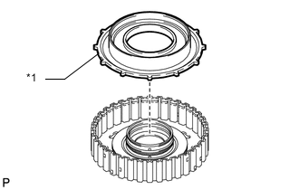
INSTALL FRONT PLANETARY RING GEAR
-
*1 Front Planetary Ring Gear Install the front planetary ring gear to the C-1 clutch assembly.
-
*a Protective Tape *b End Gap Position for Front Planetary Ring Gear Snap Ring *c Direct Multiple Disc Clutch Snap Ring Using a screwdriver, install the snap ring to the C-1 clutch assembly.
Note
-
Install so that the stop gap positions of the direct multiple disc clutch snap ring and front planetary ring gear snap ring are 180° away from each other.
-
Be careful not to damage the C-1 clutch assembly.
Tech Tips
Tape the screwdriver tip before use.
-
-
-
INSTALL FRONT PLANETARY RING GEAR WITH C-1 CLUTCH ASSEMBLY
-
*1 Thrust Bearing Race (F) Install the front planetary ring gear with C-1 clutch assembly and thrust bearing race.
Thrust Needle Roller Bearing and Thrust Bearing Race Diameter Item Inside Outside Thrust bearing race (F) 42.50 mm (1.673 in.) 58.30 mm (2.295 in.)
-
-
INSTALL C-2 CLUTCH PISTON
-
Coat the new 2 O-rings with ATF and install it to the C-2 clutch reaction sleeve sub-assembly.
-
Coat a new O-ring with ATF and install it to the O-ring to the C-2 clutch piston.
-
*1 C-2 Clutch Piston *2 C-2 Clutch Reaction Sleeve Sub-assembly *a Protrusion *b Cutout Align the protrusion of the C-2 clutch reaction sleeve sub-assembly with the cutout of the C-2 clutch piston, and install the C-2 clutch piston to the C-2 clutch reaction sleeve sub-assembly.
-
*1 No. 2 Clutch Balancer *2 Direct Clutch Return Spring Sub-assembly (C-2 clutch) Install the No. 2 clutch balancer and direct clutch return spring sub-assembly (C-2 clutch) to the C-2 clutch piston.
-
-
INSTALL NO. 2 CLUTCH DISC
-
*1 No. 2 Clutch Plate *2 No. 2 Clutch Disc *3 No. 2 Clutch Flange Install the 7 No. 2 clutch plates, 7 No. 2 clutch discs and No. 2 clutch flange to the No. 2 transmission clutch hub.
Note
Make sure that the No. 2 clutch discs, No. 2 clutch plates and No. 2 clutch flange are installed in the correct order.
-
*1 No. 2 Clutch Hub Thrust Washer *2 C-2 clutch drum sub-assembly Install the C-2 clutch drum sub-assembly and No. 2 clutch hub thrust washer to the C-2 clutch piston sub-assembly.
-
Set SST to the No. 2 clutch hub thrust washer and push on the washer using a press.
- SST
- 09223-00010
- 09950-60010 ( 09951-00550 )
-
Set SST on the No. 2 transmission clutch hub, and compress the direct clutch return spring sub-assembly (C-2 clutch) using a press.
- SST
- 09950-60010 ( 09951-00550 )
- 09350-32014 ( 09351-32040 )
-
Using SST, install the snap ring to the C-2 clutch reaction sleeve sub-assembly.
- SST
- 09350-30020 ( 09350-07070 )
-
-
INSTALL PLANETARY SUN GEAR
-
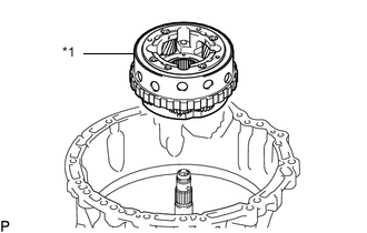
*1 Planetary Sun Gear Install the planetary sun gear to the C-2 clutch drum sub-assembly.
-
-
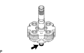
INSTALL INPUT SHAFT SUB-ASSEMBLY
-
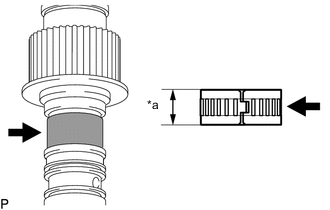
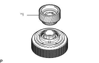
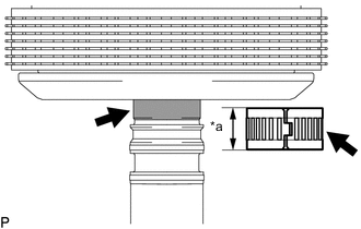
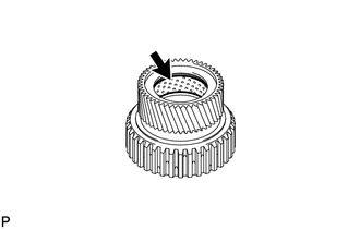
*a Width Coat a new direct disc clutch thrust needle roller bearing and input shaft sub-assembly with ATF.
Note
The bearing width is 18.1 mm (0.713 in.)
-
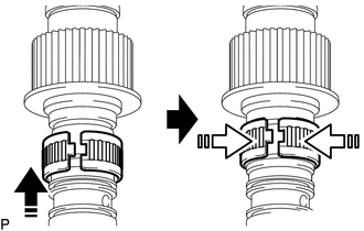
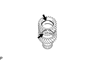
Install in this direction 
Close the opening of the bearing Install the direct disc clutch thrust needle roller bearing to the input shaft sub-assembly as shown in the illustration.
-
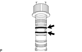
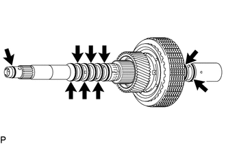
Coat the 2 new oil seal rings with ATF and install it to the input shaft sub-assembly.
-
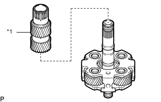
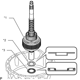
*1 Input Shaft Sub-assembly *2 Thrust Needle Roller Bearing (C) *3 Thrust Bearing Race (C) Install the input shaft sub-assembly, thrust needle roller bearing and thrust bearing race to the planetary sun gear.
Thrust Needle Roller Bearing and Thrust Bearing Race Diameter Item Inside Outside Thrust needle roller bearing (C) 37.70 mm (1.484 in.) 56.30 mm (2.217 in.) Thrust bearing race (C) 40.90 mm (1.610 in.) 60.40 mm (2.378 in.) -
*a Width Coat a new direct disc clutch thrust needle roller bearing and input shaft sub-assembly with ATF.
Note
The bearing width is 18.1 mm (0.713 in.)
-
Install in this direction Close the opening of the bearing Install the direct disc clutch thrust needle roller bearing to the input shaft sub-assembly as shown in the illustration.
-
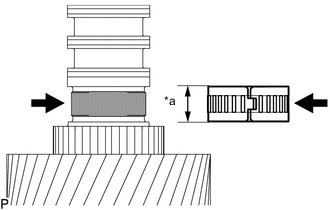
*a Width Coat a input shaft front thrust bearing and input shaft sub-assembly with ATF.
Note
The bearing width is 14.2 mm (0.559 in.)
-
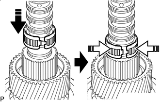
Install in this direction Close the opening of the bearing Install the input shaft front thrust bearing to the input shaft sub-assembly as shown in the illustration.
-
-
INSPECT PISTON STROKE OF NO. 2 CLUTCH
-
INSTALL C-2 CLUTCH ASSEMBLY
-
Coat the 9 new oil seal rings with ATF and install it to the C-2 clutch assembly.
-
*1 C-2 Clutch Assembly *2 Thrust Bearing Race (D) *3 Thrust Needle Roller Bearing (D) Install the C-2 clutch assembly, thrust needle roller bearing and thrust bearing race.
Thrust Needle Roller Bearing and Thrust Bearing Race Diameter Item Inside Outside Thrust bearing race (D) 40.30 mm (1.587 in.) 58.20 mm (2.291 in.) Thrust needle roller bearing (D) 43.00 mm (1.693 in.) 60.00 mm (2.362 in.)
-
-
INSTALL FRONT PLANETARY GEAR ASSEMBLY
-
*1 Front Planetary Gear Assembly Install the front planetary gear assembly to the C-2 clutch assembly.
-
-
INSTALL NO. 1 BRAKE PISTON
-
Coat the new 2 O-rings with ATF and install them to the front oil pump assembly.
-
*1 No. 1 Brake Piston *a Claw of No. 1 Brake Piston Install the No. 1 brake piston to the front oil pump assembly.
Note
Install so that the claw of the No. 1 brake piston is facing the position shown in the illustration.
-
*1 2nd Brake Return with Retainer Spring Sub-assembly Install the 2nd brake return with retainer spring sub-assembly to the front oil pump assembly.
-
Set SST on the 2nd brake return with retainer spring sub-assembly, and compress the 2nd brake return with retainer spring sub-assembly using a press.
- SST
- 09320-89010
-
Using SST, install the snap ring to the front oil pump assembly.
- SST
- 09350-30020 ( 09350-07070 )
-
-
INSTALL NO. 1 BRAKE DISC
-
*1 No. 1 Brake Disc *2 No. 1 Brake Plate *3 No. 1 Brake Flange Install the 6 No. 1 brake plates, 6 No. 1 brake discs and No. 1 brake flange to the front oil pump assembly.
Note
Make sure that the No. 1 brake discs, No. 1 brake plates and No. 1 brake flange are installed in the correct order.
-
*a Protective Tape *b Snap Ring End Gap Position Using a screwdriver, install the snap ring to the front oil pump assembly.
Note
-
The snap ring end gap position must be within the angle shown in the illustration.
-
Make sure that both ends of the snap ring are fitted into the groove.
-
Be careful not to damage the front oil pump assembly.
Tech Tips
Tape the screwdriver tip before use.
-
-
-
INSPECT PISTON STROKE OF NO. 1 BRAKE
-
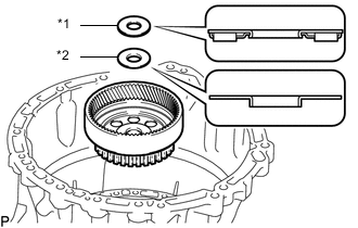
INSTALL FRONT PLANETARY SUN GEAR SUB-ASSEMBLY
-
Coat a new oil seal ring with ATF and install it to the front oil pump assembly.
-
Coat the ATF to the inside of the front planetary sun gear sub-assembly bushing.
-
*1 Front Planetary Sun Gear Sub-assembly *2 Thrust Needle Roller Bearing (A) *3 Thrust Bearing Race (A) Install the front planetary sun gear sub-assembly, thrust needle roller bearing and thrust bearing race to the front oil pump assembly.
Thrust Needle Roller Bearing and Thrust Bearing Race Diameter Item Inside Outside Thrust needle roller bearing (A) 57.40 mm (2.260 in.) 75.00 mm (2.953 in.) Thrust bearing race (A) 56.63 mm (2.230 in.) 73.00 mm (2.874 in.)
-
-
INSTALL FRONT OIL PUMP ASSEMBLY WITH FRONT PLANETARY SUN GEAR SUB-ASSEMBLY
-
Install the thrust needle roller bearing and thrust bearing race to the front planetary gear assembly.
*1 Thrust Needle Roller Bearing (B) *2 Thrust Bearing Race (B) *3 Front Oil Pump Assembly with Front Planetary Sun Gear Sub-assembly *4 Front Oil Pump Assembly *5 Front Planetary Sun Gear Sub-assembly - - Thrust Needle Roller Bearing and Thrust Bearing Race Diameter Item Inside Outside Thrust needle roller bearing (B) 56.00 mm (2.205 in.) 73.70 mm (2.902 in.) Thrust bearing race (B) 52.50 mm (2.067 in.) 71.70 mm (2.823 in.) Tech Tips
Align the knock pin on the front oil pump assembly with the knock pin hole on the automatic transmission case.
-
Insert a screwdriver through the oil pipe installation area and install the front oil pump assembly with front planetary sun gear sub-assembly while pressing on it with the screwdriver to prevent the front planetary sun gear sub-assembly from detaching from the front oil pump assembly.
Note
Be careful not to damage the front planetary sun gear sub-assembly.
-
*a Protrusion *b Groove Align the protrusion of the gear thrust washer with the groove of the front oil pump assembly, and install the gear thrust washer to the front oil pump assembly.
-
-
INSTALL FRONT OIL PUMP DRIVE SHAFT SUB-ASSEMBLY WITH DRIVE SPROCKET AND TRANSMISSION DRIVE CHAIN
-
Coat the ATF to the oil pump drive shaft sub-assembly shaft.
-
Install the oil pump drive shaft sub-assembly and drive sprocket to the transmission drive chain.
-
Install the oil pump drive shaft sub-assembly with drive sprocket and transmission drive chain to the front oil pump assembly.
-
-
INSTALL FRONT OIL PUMP OIL SEAL
-
*a -0.3 to 0.3 mm (-0.0117 to 0.0118 in.) Using SST and a hammer, install a new front oil pump oil seal to the front oil pump cover sub-assembly.
- SST
- 09950-60020 ( 09951-00810 )
- 09950-70010 ( 09951-07150 )
Standard Depth -0.3 to 0.3 mm (-0.0117 to 0.0118 in.) Note
-
Keep the front oil pump oil seal lip free of foreign matter.
-
Do not install the front oil pump oil seal at an angle.
-
When installing the front oil pump oil seal to the front oil pump cover sub-assembly, do not damage the front oil pump oil seal.
-
Coat the lip of the front oil pump oil seal with MP grease.
-
-
INSTALL FRONT OIL PUMP COVER SUB-ASSEMBLY
-
*a Protrusion *b Groove Align the protrusion of the gear thrust washer with the groove of the front oil pump cover sub-assembly, and install the gear thrust washer to the front oil pump cover sub-assembly.
Tech Tips
Apply MP grease to the installation surface of the gear thrust washer to prevent it falling off.
-
Coat a new O-ring with ATF and install it to the O-ring to the front oil pump cover sub-assembly.
-
*a Seal Packing *b Seal Diameter *c Bolt Hole *d 12.0 to 15.0 mm (0.473 to 0.590 in.) Clean the bolts and bolt installation seats of the front oil pump cover sub-assembly with solvent.
-
Apply seal packing to the front oil pump cover sub-assembly to the seating surface of each bolt as shown in the illustration.
Seal Packing Toyota Genuine Seal Packing 1281, Three Bond 1281 or equivalent Standard Seal diameter 3.0 mm (0.118 in.) or more Note
-
Do not apply seal packing inside the bolt hole.
-
Do not apply seal packing to the threaded portion of the bolt.
-
Install the bolt within 40 minutes of applying seal packing.
-
-
Install the front oil pump cover sub-assembly with the 8 bolts.
- Torque:
- 21.05 N*m { 215 kgf*cm, 16 ft.*lbf }
Tech Tips
Align the knock pin on the front oil pump assembly with the knock pin hole of the front oil pump cover sub-assembly.
-
-
INSPECT INPUT SHAFT END PLAY
-
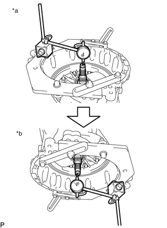
*a Input shaft facing upwards *b Input shaft facing downwards With the input shaft facing upwards, set the dial gauge to 0 mm (0 in.).
-
Set the input shaft facing downwards and measure the amount of movement of the input shaft.
Standard End Play 0.365 to 1.261 mm (0.0144 to 0.0496 in.) If the end play is not as specified, check the installation condition inside the unit.
-
-
INSPECT INDIVIDUAL PISTON OPERATION
-
INSTALL MANUAL VALVE LEVER SUB-ASSEMBLY
-
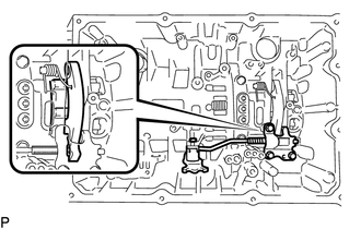
*1 Spacer *a Oil pan contact surface *b Flat surface of manual valve lever shaft Install a new spacer to the manual valve lever sub-assembly.
-
Install the manual valve lever shaft to the manual valve lever sub-assembly and automatic transmission case.
Note
Face the flat surface of the manual valve in the direction of the arrow shown in the illustration and install it.
-
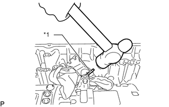
*1 Spring Pin Using a hammer, install a new spring pin to the manual valve lever shaft.
-
Turn the spacer and manual valve lever shaft to align the smaller hole on the spacer with the indent on the manual valve lever sub-assembly.
-
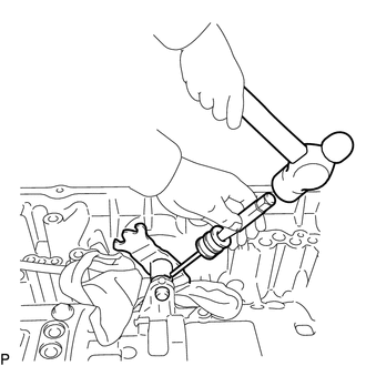
Using a 3 mm pin punch and a hammer, stake the spacer.
-
Check that the spacer does not turn.
-
-
INSTALL PARKING LOCK PAWL SHAFT
-
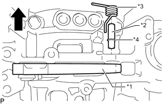
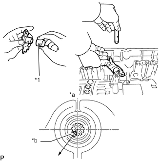
*1 Parking Lock Pawl *2 Parking Lock Pawl Shaft *3 Spring *4 E-ring 
Front Side Install the E-ring to the parking lock pawl shaft.
-
Install the parking lock pawl, parking lock pawl shaft and spring to the automatic transmission case.
-
-
INSTALL PARKING LOCK ROD SUB-ASSEMBLY
-
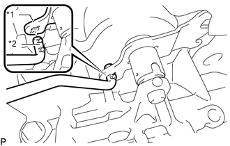
*1 Manual Valve Lever Sub-assembly *2 Parking Lock Rod Sub-assembly Install the parking lock rod sub-assembly to the manual valve lever sub-assembly.
-
-
INSTALL PARKING LOCK PAWL BRACKET
-
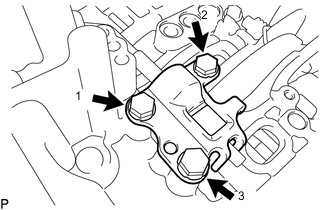
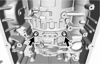
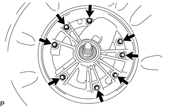
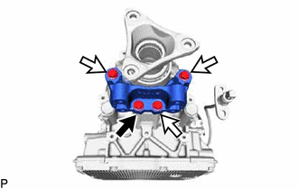
Install the parking lock pawl bracket to the automatic transmission case with the 3 bolts, in several steps in the order shown in the illustration.
- Torque:
- 18 N*m { 184 kgf*cm, 13 ft.*lbf }
-
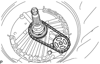
Move the manual valve lever sub-assembly to P, and check the output shaft is locked by the parking lock pawl.
-
-
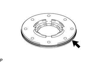
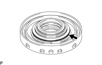
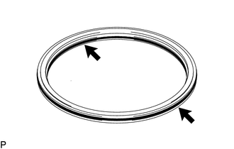
INSTALL BRAKE DRUM GASKET
-
Coat the 3 new brake drum gaskets with ATF.
-

Install the 3 brake drum gaskets to the automatic transmission case as shown in the illustration.
-
-
INSTALL OIL PUMP DELIVERY PIPE
-
Coat a new O-ring with ATF and install it to the O-ring to the oil pump delivery pipe.
-
Install the oil pump delivery pipe to the front oil pump assembly.
-
-
INSTALL OIL PUMP SUCTION PIPE
-
Coat a new O-ring with ATF and install it to the O-ring to the oil pump suction pipe.
-
Install the oil pump suction pipe to the front oil pump assembly.
-
-
INSTALL TRANSMISSION WIRE
-
INSTALL TRANSMISSION REVOLUTION SENSOR (SP2)
-
INSTALL TRANSMISSION REVOLUTION SENSOR (NT)
-
INSTALL TRANSMISSION VALVE BODY ASSEMBLY
-
INSTALL NO. 1 TRANSMISSION OIL FILLER TUBE
-
INSTALL AUTOMATIC TRANSMISSION OIL PAN SUB-ASSEMBLY
-
Coat a new oil strainer O-ring with the ATF.
-
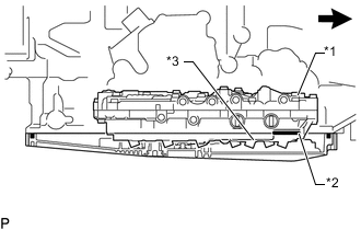
*1 Transmission Valve Body Assembly *2 O-Ring *3 Oil Strainer Front of Vehicle Insert the O-ring into the transmission valve body assembly and temporarily install the automatic transmission oil pan sub-assembly with the 12 bolts so that the transmission oil pan gasket touches the automatic transmission case.
Note
Make sure that transmission oil pan gasket seal surface and automatic transmission oil pan sub-assembly contact surface are free of oil and foreign matter.
-
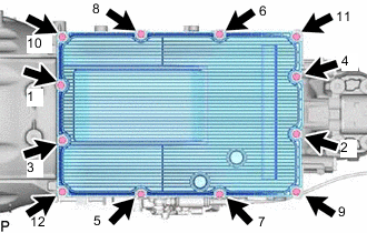
Tighten the 12 bolts in the order shown in the illustration.
- Torque:
- 7.4 N*m { 75 kgf*cm, 65 in.*lbf }
Note
-
Install the transmission oil pan gasket so that there is no slack in the transmission oil pan gasket, and the entire seal surface is level.
-
If not tightened evenly it may result in automatic transmission fluid leakage.
Tech Tips
The tightening order for the bolts are engraved near the oil pan bolt holes.
-
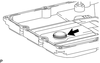
Install a new O-ring to the drain plug.
-
Using a 6 mm hexagon socket wrench, install the drain plug to the automatic transmission oil pan sub-assembly.
- Torque:
- 40 N*m { 408 kgf*cm, 30 ft.*lbf }
-
Using a 6 mm hexagon socket wrench, temporarily install the overflow plug and O-ring to the automatic transmission oil pan sub-assembly.
Tech Tips
O-ring replacement and tightening of the overflow plug are performed after the automatic transmission fluid level is adjusted.
-
Coat the gasket with ATF.
-
Temporarily install the gasket and refill plug to the automatic transmission case.
Tech Tips
Gasket replacement and tightening of the refill plug are performed after the automatic transmission fluid level is adjusted.
-
-
INSTALL AUTOMATIC TRANSMISSION FLANGE YOKE ASSEMBLY
-
Coat the lip of a new flange yoke type V oil seal with MP grease.
-
*1 Flange Yoke Type V Oil Seal *a 0 to 0.3 mm (0 to 0.0118 in.) Using SST and a hammer, install the flange yoke type V oil seal to the automatic transmission flange yoke assembly.
- SST
- 09950-60010 ( 09951-00410 )
- 09950-70010 ( 09951-07100 )
Flange Yoke Type V Oil Seal Installation Depth 0 to 0.3 mm (0 to 0.0118 in.) Note
-
Keep the flange yoke type V oil seal lip free of foreign matter.
-
Do not install the flange yoke type V oil seal at an angle.
-
When installing the flange yoke type V oil seal to the automatic transmission flange yoke assembly, do not damage the flange yoke type V oil seal.
-
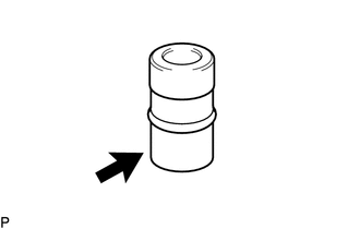
*1 Spacer *2 Rear Cover Sleeve Install the 2 spacers and rear cover sleeve to the output shaft assembly.
-
Temporarily install the automatic transmission flange yoke assembly to the output shaft with a new lock nut.
-
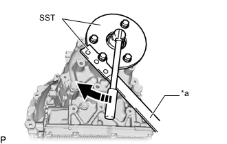
*a Hold Turn Using SST, secure the automatic transmission flange yoke assembly.
- SST
- 09330-00021
- 09950-30012 ( 09955-03040 )
Tech Tips
Use a M8 x 1.25 bolt with an under head length of 45 mm (1.77 in.) to secure SST.
-
Using a 30 mm deep socket wrench, tighten the lock nut.
- Torque:
- 135 N*m { 1377 kgf*cm, 100 ft.*lbf }
-
-
SELECT REAR COVER SLEEVE
-
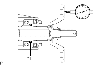
*1 Rear Cover Sleeve Using a dial indicator, measure the output shaft end play.
Standard End Play 0.21 to 0.36 mm (0.00827 to 0.0142 in.) If the end play is not as specified, select and install an appropriate rear cover sleeve that will bring the end play within the specified range.
Tech Tips
There are 15 rear cover sleeves of different thicknesses.
Rear Cover Sleeve Thickness Part No. Mark Thickness 35155-50230 00 1.675 to 1.725 mm (0.0659 to 0.0679 in.) 35155-50080 02 1.725 to 1.775 mm (0.0679 to 0.0699 in.) 35155-50090 03 1.775 to 1.825 mm (0.0699 to 0.0719 in.) 35155-50100 04 1.825 to 1.875 mm (0.0719 to 0.0738 in.) 35155-50110 05 1.875 to 1.925 mm (0.0738 to 0.0758 in.) 35155-50120 06 1.925 to 1.975 mm (0.0758 to 0.0778 in.) 35155-50130 07 1.975 to 2.025 mm (0.0778 to 0.0797 in.) 35155-50140 08 2.025 to 2.075 mm (0.0797 to 0.0817 in.) 35155-50150 09 2.075 to 2.125 mm (0.0817 to 0.0837 in.) 35155-50160 10 2.125 to 2.175 mm (0.0837 to 0.0856 in.) 35155-50170 11 2.175 to 2.225 mm (0.0856 to 0.0876 in.) 35155-50180 12 2.225 to 2.275 mm (0.0876 to 0.0896 in.) 35155-50190 13 2.275 to 2.325 mm (0.0896 to 0.0915 in.) 35155-50200 14 2.325 to 2.375 mm (0.0915 to 0.0935 in.) 35155-50210 15 2.375 to 2.425 mm (0.0935 to 0.0955 in.) -
Using a chisel and hammer, securely stake the lock nut.
-
-
INSTALL TRANSMISSION CASE ADAPTER
-
Bolt A 
Bolt B Install the transmission case adapter to the automatic transmission case with the 4 bolts.
- Torque:
- 48.5 N*m { 495 kgf*cm, 36 ft.*lbf }
Note
After tightening the bolt A, tighten bolt B.
-
-
INSTALL OIL COOLER TUBE UNION
-
Coat the 2 new O-rings with ATF and install them to the 2 oil cooler tube unions.
-

*a 22 to 26° *b 1 to 5° *c Hold *d Torque Wrench Fulcrum Length Turn Using SST, install the 2 oil cooler tube unions to the automatic transmission case.
- SST
- 09268-78010
- Torque:
- Specified tightening torque
- 31.1 N*m { 317 kgf*cm, 23 ft.*lbf }
Tech Tips
-
Calculate the torque wrench reading when changing the fulcrum length of the torque wrench
-
When using SST (fulcrum length of 34.5 mm (1.3583 in.)) + torque wrench (fulcrum length of 180 mm (7.0866 in.)): 26.1 N*m (266 kgf*cm, 19 ft.*lbf)
-
-
INSTALL SHIFT CONTROL ACTUATOR ASSEMBLY
-
INSTALL NO. 1 BREATHER PLUG (ATM)
-
Apply a light coat of ATF to the O-ring of the No. 1 breather plug (ATM).
-
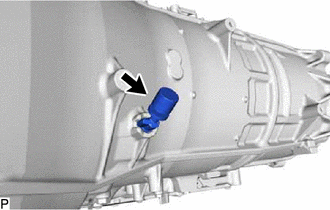
Install the No. 1 breather plug (ATM) to the automatic transmission case.
-