PARKING LOCK RELEASE CABLE INSTALLATION
CAUTION / NOTICE / HINT
Note
The parking shift lock release stopper used to prevent improper installation that is included with the parking lock release lever supply part is removed in the throttle link connecting rod assembly installation procedure.
PROCEDURE
-
INSTALL NO. 2 PARKING RELEASE CABLE BRACKET SUB-ASSEMBLY
Tech Tips
There is no need to remove this unless the No. 2 parking release cable bracket sub-assembly is replaced.
-
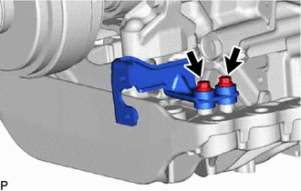
Install the No. 2 parking release cable bracket sub-assembly to the engine rear mounting member with the 2 bolts.
- Torque:
- 7.5 N*m { 76 kgf*cm, 66 in.*lbf }
-
-
INSTALL PARKING LOCK RELEASE LEVER ASSEMBLY
-
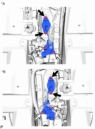
*A for LHD *B for RHD 
Bolt A 
Bolt B Pass the parking lock release lever assembly through the floor panel through holes and install it with the 4 bolts.
Tech Tips
-
Do not damage the cable with the floor panel through holes.
-
Do not bend the cable.
- Torque:
- for bolt A
- 12 N*m { 122 kgf*cm, 9 ft.*lbf }
- for bolt B
- 14.5 N*m { 148 kgf*cm, 11 ft.*lbf }
-
-
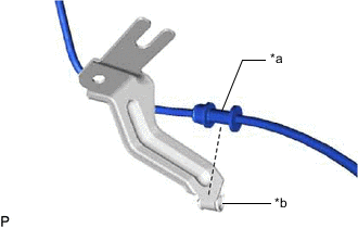
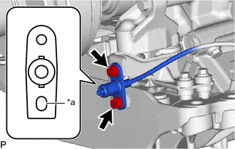
*a Protector *b Clamp Install the No. 1 parking lock release cable clamp bracket to the parking lock release lever assembly protector.
Note
Securely install the protector into the clamp.
-
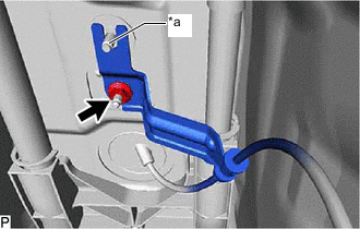
*a Stopper Install the No. 1 parking lock release cable clamp bracket to the body with the nut.
- Torque:
- 8.0 N*m { 82 kgf*cm, 71 in.*lbf }
Note
The rear side of the floor stud bolt is used as a stopper. Therefore, install the nut to the front side.
-
-
INSTALL TRANSMISSION LEVER OUTER
-
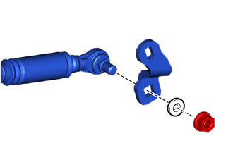
Install the transmission lever outer to the throttle link connecting rod assembly with the nut and spring washer.
- Torque:
- 12.7 N*m { 130 kgf*cm, 9 ft.*lbf }
-
-
INSTALL THROTTLE LINK CONNECTING ROD ASSEMBLY
-
*a Long Hole Install the throttle link connecting rod assembly to the No. 2 parking release cable bracket sub-assembly with the 2 bolts.
- Torque:
- 7.5 N*m { 76 kgf*cm, 66 in.*lbf }
Note
Install so that the long hole is at the bottom side of the vehicle.
-
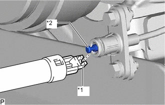
*1 Parking Lock Release Lever Assembly Cable End *2 Throttle Link Connecting Rod Assembly Cable End Connect the parking lock release lever assembly cable end to the throttle link connecting rod assembly cable end.
-
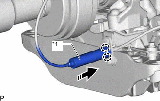
*1 Cover 
Connect Attach the 2 claws and connect the cover to the throttle link connecting rod assembly as shown in the illustration.
-
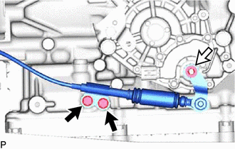
Bolt Nut and Spring Washer Connect the throttle link connecting rod assembly to the shift control actuator assembly with the nut, spring washer and 2 bolts.
- Torque:
- for bolt
- 12 N*m { 122 kgf*cm, 9 ft.*lbf }
- for nut
- 12.7 N*m { 130 kgf*cm, 9 ft.*lbf }
-
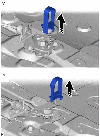
*A for LHD *B for RHD Remove Remove the parking shift lock release stopper used to prevent improper installation from the parking lock release lever assembly.
Tech Tips
The parking shift lock release stopper used to prevent improper installation is only included with supply parts.
-
-
INSTALL UPPER NO. 1 CONSOLE SUPPORT BRACKET
-
INSTALL FRONT NO. 1 FLOOR HEAT INSULATOR
-
INSTALL NO. 1 CONSOLE BOX SUPPORT