SHIFT CONTROL ECU INSTALLATION
PROCEDURE
-
INSTALL NO. 2 SHIFT CONTROL ECU BRACKET
-
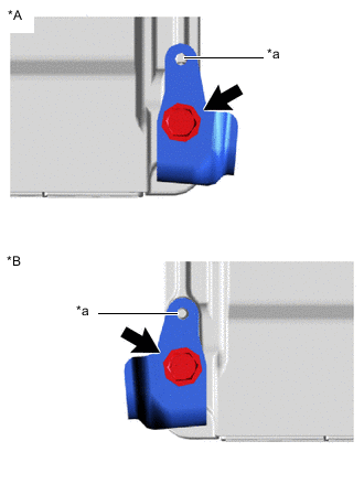
*A for LHD *B for RHD *a Align the hole on the No. 2 shift control ECU bracket with the protrusion of the shift control ECU. Install the No. 2 shift control ECU bracket to the shift control ECU with the bolt.
- Torque:
- 4.5 N*m { 46 kgf*cm, 40 in.*lbf }
Note
Do not deform the No. 2 shift control ECU bracket.
-
-
INSTALL NO. 1 SHIFT CONTROL ECU BRACKET
-
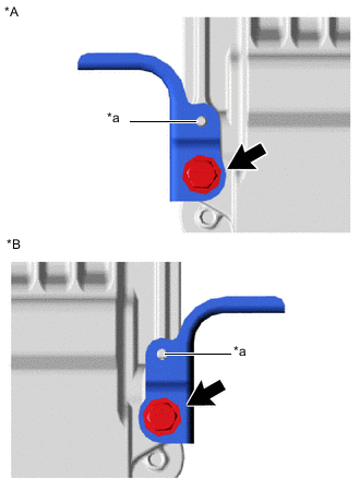
*A for LHD *B for RHD *a Align the hole on the No. 1 shift control ECU bracket with the protrusion of the shift control ECU. Install the No. 1 shift control ECU bracket to the shift control ECU with the bolt.
- Torque:
- 4.5 N*m { 46 kgf*cm, 40 in.*lbf }
Note
Do not deform the No. 1 shift control ECU bracket.
-
-
INSTALL SHIFT CONTROL ECU
-
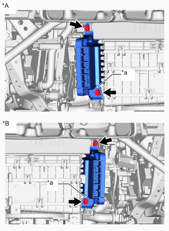
*A for LHD *B for RHD *a Align the hole on the No. 2 shift control ECU bracket with the protrusion of the air conditioning unit. Install the shift control ECU with the 2 bolts.
- Torque:
- 7.5 N*m { 76 kgf*cm, 66 in.*lbf }
Note
Do not deform the No. 1 shift control ECU bracket and No. 2 shift control ECU bracket when installing the shift control ECU.
-
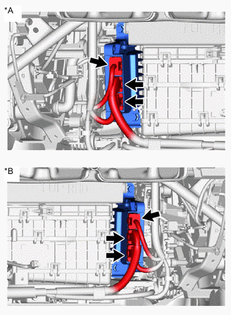
*A for LHD *B for RHD Connect the 3 shift control ECU connectors.
-
-
INSTALL NO. 1 AIR DUCT (for RHD)
-
INSTALL NO. 2 AIR DUCT (for LHD)
-
INSTALL GLOVE COMPARTMENT DOOR ASSEMBLY
-
CONNECT CABLE TO NEGATIVE BATTERY TERMINAL
Note
When disconnecting the cable, some systems need to be initialized after the cable is reconnected.
-
CHECK AND CLEAR DTC
-
INSTALL NO. 2 DECK BOARD
-
CHECK SRS WARNING LIGHT