ELECTRONIC SHIFT LEVER SYSTEM "P" Position Switch Circuit
PROCEDURE
-
CHECK DTC OUTPUT (TRANSMISSION)
-
Connect the GTS to the DLC3.
-
Turn the engine switch on (IG).
-
Depress the brake pedal and move the shift lever to select neutral (N).
-
Push the P position switch (shift position indicator) to select park (P).
-
Jiggle the connectors and wire harness that connect the P position switch (shift position indicator) to the P1 terminal of the shift control ECU up and down, and left and right.
-
Enter the following menus: Powertrain / Transmission / Trouble Codes.
Powertrain > Transmission > Trouble Codes -
Check for DTCs.
Result Result Proceed to None of the DTCs are output. A Any of the DTCs are output. B -
Turn the engine switch off.
B 
GO TO DTC CHART Click here
A 
-
-
CHECK DIAGNOSIS RELATED INFORMATION (TRANSMISSION)
-
Connect the GTS to the DLC3.
-
Turn the engine switch on (IG).
-
Turn the GTS on.
-
Enter the following menus: Powertrain / Transmission / Utility / Diagnosis Related Information.
Powertrain > Transmission > UtilityTester Display Diagnosis Related Information -
Check for diagnosis related information.
Result Result Proceed to No diagnosis related information is output. A The diagnosis related information in the table below is output. B Diagnosis Related Information P085011 P085015 -
Turn the engine switch off.
A
CHECK FOR INTERMITTENT PROBLEMS Click here
B
-
-
CHECK CONNECTOR CONNECTION CONDITION (P POSITION SWITCH (SHIFT POSITION INDICATOR) CONNECTOR)
-
Check the connector connections and contact pressure of the relevant terminals for the P position switch (shift position indicator) connector.
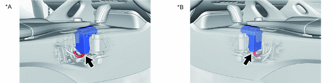
*A for RHD *B for LHD OK The connector is connected securely and there are no contact pressure problems. Result Proceed to OK NG
NG
CONNECT SECURELY
OK
-
-
CHECK CONNECTOR CONNECTION CONDITION (SHIFT CONTROL ECU CONNECTOR)
-
Check the connector connections and contact pressure of the relevant terminals for the shift control ECU connectors.
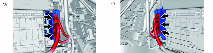
*A for RHD *B for LHD OK The connectors are connected securely and there are no contact pressure problems. Result Proceed to OK NG
NG
CONNECT SECURELY
OK
-
-
CHECK HARNESS AND CONNECTOR (SHIFT CONTROL ECU - P POSITION SWITCH (SHIFT POSITION INDICATOR))
-
Disconnect the P75 shift control ECU connector.
-
Disconnect the P39 P position switch (shift position indicator) connector.
-
Measure the resistance according to the value(s) in the table below.
Standard Resistance (Check for Open) Tester Connection Condition Specified Condition P75-10 (P1) - P39-14 (S) Always Below 1 Ω Standard Resistance (Check for Short) Tester Connection Condition Specified Condition P75-10 (P1) or P39-14 (S) - Body ground and other terminals Always 10 kΩ or higher -
Reconnect the P39 P position switch (shift position indicator) connector.
-
Reconnect the P75 shift control ECU connector.
Result Proceed to OK NG
OK
CHECK FOR INTERMITTENT PROBLEMS Click here
NG
REPAIR OR REPLACE HARNESS OR CONNECTOR
-