ELECTRONIC SHIFT LEVER SYSTEM "Shift system malfunction See owner's manual" is Displayed on Multi-information Display
CAUTION / NOTICE / HINT
Note
-
After turning the engine switch off, waiting time may be required before disconnecting the cable from the negative (-) battery terminal. Therefore, make sure to read the disconnecting the cable from the negative (-) battery terminal notices before proceeding with work.
-
The vehicle is equipped with a sub-battery. Therefore, ensure there is no power being supplied to the vehicle when disconnecting or reconnecting the connector of the shift control ECU and when removing or installing the shift control ECU.
PROCEDURE
-
READ VALUE USING GTS (RANGE SENSOR VOLTAGE)
-
Connect the GTS to the DLC3.
-
Turn the engine switch on (IG).
-
Enter the following menus: Powertrain / Transmission / Data List / Park Pawl Position Sensor Voltage "A", Park Pawl Position Sensor Voltage "B".
Powertrain > Transmission > Data ListTester Display Park Pawl Position Sensor Voltage "A" Park Pawl Position Sensor Voltage "B" -
Read the Data List according to the display on the GTS.
Result Data List Item Condition Specified Condition Park Pawl Position Sensor Voltage "A" Shift state park (P) (15 to 35°C (59 to 95°F)) 1.35 to 1.81 V Park Pawl Position Sensor Voltage "B" Shift state park (P) (15 to 35°C (59 to 95°F)) 3.02 to 3.85 V -
Turn the engine switch off.
Result Proceed to OK NG
NG 
GO TO STEP 4 Click here
OK 
-
-
CHECK DTC OUTPUT (TRANSMISSION)
-
Connect the GTS to the DLC3.
-
Turn the engine switch on (IG).
-
Depress the brake pedal and move the shift lever to select neutral (N).
-
Enter the following menus: Powertrain / Transmission / Trouble Codes.
Powertrain > Transmission > Trouble Codes -
Check if DTCs are output.
Result Result Proceed to None of the DTCs are output. A Any of the DTCs are output. B -
Push the P position switch (shift position indicator) to select park (P).
-
Turn the engine switch off.
B 
GO TO DTC CHART Click here
A
-
-
READ VALUE USING GTS (RANGE SENSOR VOLTAGE)
-
Connect the GTS to the DLC3.
-
Turn the engine switch on (IG).
-
Depress the brake pedal and move the shift lever to select neutral (N).
-
Enter the following menus: Powertrain / Transmission / Data List / Park Pawl Position Sensor Voltage "A", Park Pawl Position Sensor Voltage "B".
Powertrain > Transmission > Data ListTester Display Park Pawl Position Sensor Voltage "A" Park Pawl Position Sensor Voltage "B" -
Read the Data List according to the display on the GTS.
Result Data List Item Condition Specified Condition Park Pawl Position Sensor Voltage "A" Shift state neutral (N) (15 to 35°C (59 to 95°F)) 3.02 to 3.85 V Park Pawl Position Sensor Voltage "B" Shift state neutral (N) (15 to 35°C (59 to 95°F)) 1.35 to 1.81 V -
Push the P position switch (shift position indicator) to select park (P).
-
Turn the engine switch off.
Result Proceed to OK NG
OK
CHECK FOR INTERMITTENT PROBLEMS Click here
NG
-
-
CHECK HARNESS AND CONNECTOR (SHIFT CONTROL ECU - RANGE SENSOR (SHIFT CONTROL ACTUATOR ASSEMBLY))
-
Disconnect the A53 shift control ECU connector.
-
Disconnect the G46 range sensor (shift control actuator assembly) connector.
-
Measure the resistance according to the value(s) in the table below.
Standard Resistance (Check for Open) Tester Connection Condition Specified Condition A53-19 (VCNS) - G46-1 (VCNS) Always Below 1 Ω A53-20 (NS1) - G46-2 (NS1) Always Below 1 Ω A53-18 (NS2) - G46-4 (NS2) Always Below 1 Ω A53-17 (E2NS) - G46-3 (E2NS) Always Below 1 Ω Standard Resistance (Check for Short) Tester Connection Condition Specified Condition A53-19 (VCNS) or G46-1 (VCNS) - Body ground and other terminals Always 10 kΩ or higher A53-20 (NS1) or G46-2 (NS1) - Body ground and other terminals Always 10 kΩ or higher A53-18 (NS2) or G46-4 (NS2) - Body ground and other terminals Always 10 kΩ or higher A53-17 (E2NS) or G46-3 (E2NS) - Body ground and other terminals Always 10 kΩ or higher -
Reconnect the G46 range sensor (shift control actuator assembly) connector.
-
Reconnect the A53 shift control ECU connector.
Result Proceed to OK NG
NG
REPAIR OR REPLACE HARNESS OR CONNECTOR
OK
-
-
CHECK SHIFT CONTROL ECU (VCNS VOLTAGE)
-
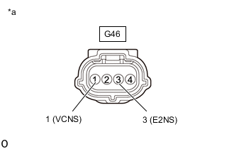
*a Front view of wire harness connector
(to Range Sensor (Shift Control Actuator Assembly))
Disconnect the range sensor (shift control actuator assembly) connector.
-
Turn the engine switch on (IG).
-
Measure the voltage according to the value(s) in the table below.
Standard Voltage Tester Connection Switch Condition Specified Condition G46-1 (VCNS) - G46-3 (E2NS) Engine switch on (IG) 4.5 to 5.5 V Note
Turning the engine switch on (IG) with the connector disconnected causes other DTCs to be stored. Clear the DTCs after performing this inspection.
-
Turn the engine switch off.
-
Reconnect the range sensor (shift control actuator assembly) connector.
Result Proceed to OK NG
NG
REPLACE SHIFT CONTROL ECU Click here
OK
-
-
CHECK SHIFT CONTROL ECU (NS1, NS2 VOLTAGE)
-
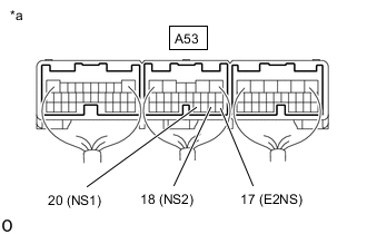
*a Component with harness connected
(Shift Control ECU)
Turn the engine switch on (IG).
-
Measure the voltage according to the value(s) in the table below.
Standard Voltage Tester Connection Condition Specified Condition A53-20 (NS1) - A53-17 (E2NS) Shift state park (P) 1.35 to 1.81 V Shift state neutral (N) 3.02 to 3.85 V A53-18 (NS2) - A53-17 (E2NS) Shift state park (P) 3.02 to 3.85 V Shift state neutral (N) 1.35 to 1.81 V -
Turn the engine switch off.
Result Proceed to OK NG
OK
REPLACE SHIFT CONTROL ECU Click here
NG
-
-
CHECK SHIFT CONTROL ECU (CHECK RESISTANCE)
-
Check that the voltage between the terminals of the sub-battery module assembly is 0 V.
-
Disconnect the cable from the negative (-) battery terminal.
-
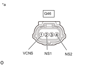
*a Front view of wire harness connector
(to Range Sensor (Shift Control Actuator Assembly))
Disconnect the range sensor (shift control actuator assembly) connector.
-
Measure the resistance according to the value(s) in the table below.
Standard Resistance Tester Connection Condition Specified Condition G46-2 (NS1) - G46-1 (VCNS) 20°C (68°F) 180 to 220 kΩ G46-4 (NS2) - G46-1 (VCNS) 20°C (68°F) 180 to 220 kΩ -
Reconnect the range sensor (shift control actuator assembly) connector.
-
Reconnect the cable to the negative (-) battery terminal.
Result Proceed to OK NG
OK
REPLACE SHIFT CONTROL ACTUATOR ASSEMBLY Click here
NG
REPLACE SHIFT CONTROL ECU Click here
-