ELECTRONIC SHIFT LEVER SYSTEM, Diagnostic DTC:P08A600, P08A662, P183411, P183415, P183A11, P183A15, P183F12, P183F14, P184512, P184514
| DTC Code | DTC Name |
|---|---|
| P08A600 | Gear Lever Position Sensor Correlation Failure |
| P08A662 | Gear Lever Position Sensor Signal Compare Failure |
| P183411 | Gear Lever Y Position Sensor 1 Circuit Short to Ground |
| P183415 | Gear Lever Y Position Sensor 1 Circuit Short to Battery or Open |
| P183A11 | Gear Lever Y Position Sensor 2 Circuit Short to Ground |
| P183A15 | Gear Lever Y Position Sensor 2 Circuit Short to Battery or Open |
| P183F12 | Gear Lever X Position Sensor 1 Circuit Short to Battery |
| P183F14 | Gear Lever X Position Sensor 1 Circuit Short to Ground or Open |
| P184512 | Gear Lever X Position Sensor 2 Circuit Short to Battery |
| P184514 | Gear Lever X Position Sensor 2 Circuit Short to Ground or Open |
DESCRIPTION
Tech Tips
-
The electronic shift lever system is a linkless type that does not use a shift cable.
-
The shift and select sensors are non-contact type sensors.
The shift lever (transmission floor shift assembly) is a momentary type, which returns to its home position by spring tension as the driver's hand is released from the shift lever after shifting.
The shift lever (transmission floor shift assembly) contains a shift lever position sensor to detect the shift lever position (Home, R, N, D or M). Because the shift lever position sensor operates using Hall ICs, they can accurately detect the shift lever position in a reliable manner.
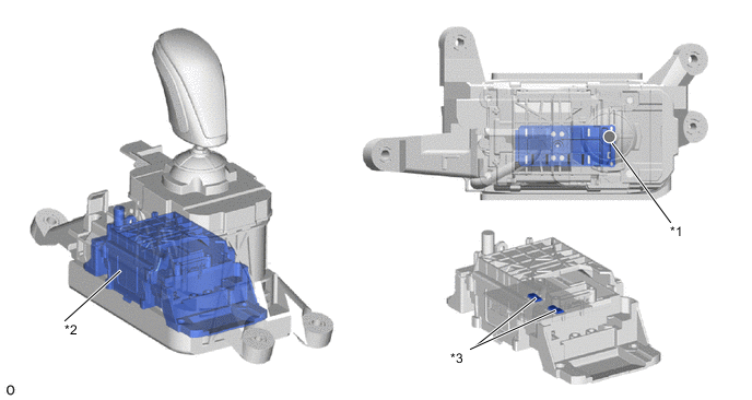
| *1 | Magnet Shift Position |
| *2 | Shift Lever Position Sensor |
| *3 | Hall IC |
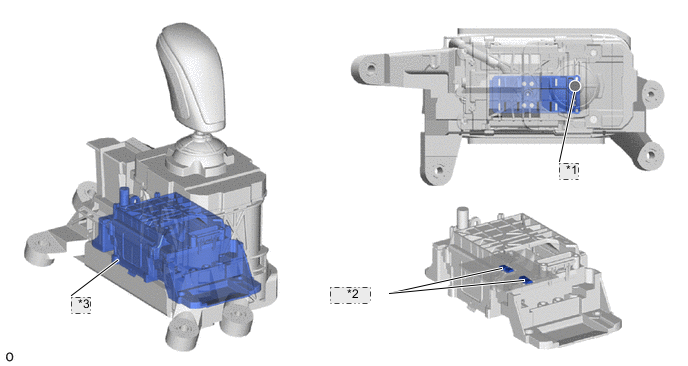
| *1 | Magnet Shift Position |
| *2 | Hall IC |
| *3 | Shift Lever Position Sensor |
| DTC No. | Detection Item | DTC Detection Condition | Trouble Area | MIL | Warning Indicate |
|---|---|---|---|---|---|
| P08A600 | Gear Lever Position Sensor Correlation Failure | The engine switch on (IG) and shift sensor pattern malfunction (VSI1, VSI2, VSI3 and VSI4 High/Low combination malfunction) continuously occurs for 3 seconds or more (1 trip detection logic) |
|
Comes on |
|
| P08A662 | Gear Lever Position Sensor Signal Compare Failure | The engine switch on (IG) and battery voltage is 10 V or higher, shift sensor pattern malfunction (VSI1, VSI2, VSI3 or VSI4 value outside specified range) continuously occurs for 3 seconds or more (1 trip detection logic) |
|
Comes on |
|
| P183411 | Gear Lever Y Position Sensor 1 Circuit Short to Ground | The engine switch on (IG) and battery voltage is 10 V or higher, VSI1 terminal voltage is below 0.3 V continuously for 3 seconds or more (1 trip detection logic) |
|
Comes on |
|
| P183415 | Gear Lever Y Position Sensor 1 Circuit Short to Battery or Open | The engine switch on (IG) and battery voltage is 10 V or higher, VSI1 terminal voltage is higher than 4.68 V continuously for 3 seconds or more (1 trip detection logic) |
|
Comes on |
|
| P183A11 | Gear Lever Y Position Sensor 2 Circuit Short to Ground | The engine switch on (IG) and battery voltage is 10 V or higher, VSI2 terminal voltage is below 0.6 V continuously for 3 seconds or more (1 trip detection logic) |
|
Comes on |
|
| P183A15 | Gear Lever Y Position Sensor 2 Circuit Short to Battery or Open | The engine switch on (IG) and battery voltage is 10 V or higher, VSI2 terminal voltage is higher than 4.4 V continuously for 3 seconds or more (1 trip detection logic) |
|
Comes on |
|
| P183F12 | Gear Lever X Position Sensor 1 Circuit Short to Battery | The engine switch on (IG) and battery voltage is 10 V or higher, VSI3 terminal voltage is higher than 4.4 V continuously for 3 seconds or more (1 trip detection logic) |
|
Comes on |
|
| P183F14 | Gear Lever X Position Sensor 1 Circuit Short to Ground or Open | The engine switch on (IG) and battery voltage is 10 V or higher, VSI3 terminal voltage is below 0.6 V continuously for 3 seconds or more (1 trip detection logic) |
|
Comes on |
|
| P184512 | Gear Lever X Position Sensor 2 Circuit Short to Battery | The engine switch on (IG) and battery voltage is 10 V or higher, VSI4 terminal voltage is higher than 4.68 V continuously for 3 seconds or more (1 trip detection logic) |
|
Comes on |
|
| P184514 | Gear Lever X Position Sensor 2 Circuit Short to Ground or Open | The engine switch on (IG) and battery voltage is 10 V or higher, VSI4 terminal voltage is below 0.3 V continuously for 3 seconds or more (1 trip detection logic) |
|
Comes on |
|
Shift lever position sensor pattern malfunctions are detected when a logical inconsistency is detected by comparing each shift lever position sensor signal with the determined shift position. The detection pattern is as follows:
| Shift Lever Position Sensor Signal | VSI1 | VSI2 | VSI3 | VSI4 | Malfunction Detection |
|---|---|---|---|---|---|
| Input Voltage | Low | Low | High | High | Normal |
| High | High | Low | Low | Normal | |
| Low | High | Low | High | Abnormal | |
| High | Low | High | Low | Abnormal |
Tech Tips
-
Low: below 2.5 V
-
High: 2.5 V or higher
| Shift Lever Position Sensor Signal | Input Voltage | Malfunction Detection |
|---|---|---|
| VSI1 ←→ VSI2 | Voltage difference 0.742 V or higher | Abnormal |
| VSI2 ←→ VSI3 | Voltage difference 1.952 V or higher | Abnormal |
| VSI3 ←→ VSI4 | Voltage difference 0.742 V or higher | Abnormal |
| VSI1 ←→ VSI3 | Voltage difference 2.502 V or higher | Abnormal |
| VSI2 ←→ VSI4 | Voltage difference 2.502 V or higher | Abnormal |
| VSI1 ←→ VSI4 | Voltage difference 3.052 V or higher | Abnormal |
CONFIRMATION DRIVING PATTERN
Tech Tips
After repairs have been completed, clear the DTCs and then check that the vehicle has returned to normal by performing the All Readiness check procedure.
-
Start the engine.
-
With the brake pedal depressed, slowly move the shift lever as follows to select each shift state: N → R → N → D → M → Home.
-
Push the P position switch (shift position indicator) to select park (P).
WIRING DIAGRAM
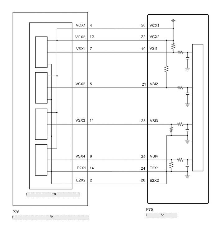
| *a | Shift Lever Position Sensor |
| *b | Shift Lever Position Sensor (Transmission Floor Shift Assembly) |
| *c | Shift Control ECU |
CAUTION / NOTICE / HINT
Note
-
After turning the engine switch off, waiting time may be required before disconnecting the cable from the negative (-) battery terminal. Therefore, make sure to read the disconnecting the cable from the negative (-) battery terminal notices before proceeding with work.
-
The vehicle is equipped with a sub-battery. Therefore, ensure there is no power being supplied to the vehicle when disconnecting or reconnecting the connector of the shift control ECU and when removing or installing the shift control ECU.
PROCEDURE
-
READ VALUE USING GTS (SHIFT LEVER POSITION SENSOR VOLTAGE)
-
Connect the GTS to the DLC3.
-
Start the engine.
-
Enter the following menus: Powertrain / Transmission / Data List / Shift Sensor Voltage (VSI1) (Gear Shift Control Module), Shift Sensor Voltage (VSI2) (Gear Shift Control Module), Shift Sensor Voltage (VSI3) (Gear Shift Control Module), Shift Sensor Voltage (VSI4) (Gear Shift Control Module).
Powertrain > Transmission > Data ListTester Display Shift Sensor Voltage (VSI1) (Gear Shift Control Module) Shift Sensor Voltage (VSI2) (Gear Shift Control Module) Shift Sensor Voltage (VSI3) (Gear Shift Control Module) Shift Sensor Voltage (VSI4) (Gear Shift Control Module) -
With the brake pedal depressed, slowly move the shift lever as follows: N → R → N → D → M → Home.
Tech Tips
Wait with the shift lever in each position for 5 seconds or more.
-
Read the Data List according to the display on the GTS.
Result Data List Item Shift Lever Position D N R M Home Shift Sensor Voltage (VSI1) (Gear Shift Control Module) 1.366 to 1.923 V 0.774 to 1.366 V 0.3 to 0.774 V 2.5 to 3.634 V 3.634 to 4.226 V Shift Sensor Voltage (VSI2) (Gear Shift Control Module) 2.08 to 2.5 V 1.324 to 2.08 V 0.3 to 1.324 V 2.5 to 3.084 V 3.084 to 3.676 V Shift Sensor Voltage (VSI3) (Gear Shift Control Module) 3.676 to 4.75 V 2.92 to 3.676 V 2.5 to 2.92 V 0.3 to 1.324 V 1.324 to 1.916 V Shift Sensor Voltage (VSI4) (Gear Shift Control Module) 4.226 to 4.75 V 3.634 to 4.226 V 3.077 to 3.634 V 0.3 to 0.774 V 0.774 to 1.366 V -
Push the P position switch (shift position indicator) to select park (P).
-
Turn the engine switch off.
Result Proceed to OK NG
OK 
CHECK FOR INTERMITTENT PROBLEMS Click here
NG 
-
-
CHECK HARNESS AND CONNECTOR (SHIFT CONTROL ECU - SHIFT LEVER POSITION SENSOR (TRANSMISSION FLOOR SHIFT ASSEMBLY))
-
Disconnect the P75 shift control ECU connector.
-
Disconnect the P76 shift lever position sensor (transmission floor shift assembly) connector.
-
Measure the resistance according to the value(s) in the table below.
Standard Resistance (Check for Open) Tester Connection Condition Specified Condition P75-20 (VCX1) - P76-4 (VCX1) Always Below 1 Ω P75-22 (VCX2) - P76-12 (VCX2) Always Below 1 Ω P75-19 (VSI1) - P76-7 (VSX1) Always Below 1 Ω P75-21 (VSI2) - P76-5 (VSX2) Always Below 1 Ω P75-23 (VSI3) - P76-11 (VSX3) Always Below 1 Ω P75-25 (VSI4) - P76-9 (VSX4) Always Below 1 Ω P75-24 (E2X1) - P76-14 (E2X1) Always Below 1 Ω P75-26 (E2X2) - P76-2 (E2X2) Always Below 1 Ω Standard Resistance (Check for Short) Tester Connection Condition Specified Condition P75-20 (VCX1) or P76-4 (VCX1) - Body ground and other terminals Always 10 kΩ or higher P75-22 (VCX2) or P76-12 (VCX2) - Body ground and other terminals Always 10 kΩ or higher P75-19 (VSI1) or P76-7 (VSX1) - Body ground and other terminals Always 10 kΩ or higher P75-21 (VSI2) or P76-5 (VSX2) - Body ground and other terminals Always 10 kΩ or higher P75-23 (VSI3) or P76-11 (VSX3) - Body ground and other terminals Always 10 kΩ or higher P75-25 (VSI4) or P76-9 (VSX4) - Body ground and other terminals Always 10 kΩ or higher P75-24 (E2X1) or P76-14 (E2X1) - Body ground and other terminals Always 10 kΩ or higher P75-26 (E2X2) or P76-2 (E2X2) - Body ground and other terminals Always 10 kΩ or higher -
Reconnect the P76 shift lever position sensor (transmission floor shift assembly) connector.
-
Reconnect the P75 shift control ECU connector.
Result Proceed to OK NG
NG
REPAIR OR REPLACE HARNESS OR CONNECTOR
OK
-
-
CHECK SHIFT CONTROL ECU (VCX1, VCX2 VOLTAGE)
-
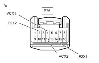
*a Front view of wire harness connector
(to Shift Lever Position Sensor (Transmission Floor Shift Assembly))
Disconnect the shift lever position sensor (transmission floor shift assembly) connector.
-
Turn the engine switch on (IG).
-
Measure the voltage according to the value(s) in the table below.
Standard Voltage Tester Connection Switch Condition Specified Condition P76-4 (VCX1) - P76-14 (E2X1) Engine switch on (IG) 4.5 to 5.5 V P76-12 (VCX2) - P76-2 (E2X2) Engine switch on (IG) 4.5 to 5.5 V Note
Turning the engine switch on (IG) with the connector disconnected causes other DTCs to be stored. Clear the DTCs after performing this inspection.
-
Turn the engine switch off.
-
Reconnect the shift lever position sensor (transmission floor shift assembly) connector.
Result Proceed to OK NG
NG
REPLACE SHIFT CONTROL ECU Click here
OK
-
-
CHECK SHIFT CONTROL ECU (VSI1, VSI2, VSI3, VSI4 VOLTAGE)
-
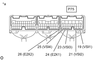
*a Component with harness connected
(Shift Control ECU)
Turn the engine switch on (IG).
-
Measure the voltage according to the value(s) in the table below.
Standard Voltage Tester Connection Condition Specified Condition P75-19 (VSI1) - P75-24 (E2X1) Engine switch on (IG), shift lever in D 1.366 to 1.923 V Engine switch on (IG), shift lever in N 0.774 to 1.366 V Engine switch on (IG), shift lever in R 0.3 to 0.774 V Engine switch on (IG), shift lever in M 2.5 to 3.634 V Engine switch on (IG), shift lever in home position 3.634 to 4.226 V P75-21 (VSI2) - P75-24 (E2X1) Engine switch on (IG), shift lever in D 2.08 to 2.5 V Engine switch on (IG), shift lever in N 1.324 to 2.08 V Engine switch on (IG), shift lever in R 0.3 to 1.324 V Engine switch on (IG), shift lever in M 2.5 to 3.084 V Engine switch on (IG), shift lever in home position 3.084 to 3.676 V P75-23 (VSI3) - P75-26 (E2X2) Engine switch on (IG), shift lever in D 3.676 to 4.75 V Engine switch on (IG), shift lever in N 2.92 to 3.676 V Engine switch on (IG), shift lever in R 2.5 to 2.92 V Engine switch on (IG), shift lever in M 0.3 to 1.324 V Engine switch on (IG), shift lever in home position 1.324 to 1.916 V P75-25 (VSI4) - P75-26 (E2X2) Engine switch on (IG), shift lever in D 4.226 to 4.75 V Engine switch on (IG), shift lever in N 3.634 to 4.226 V Engine switch on (IG), shift lever in R 3.077 to 3.634 V Engine switch on (IG), shift lever in M 0.3 to 0.774 V Engine switch on (IG), shift lever in home position 0.774 to 1.366 V -
Turn the engine switch off.
Result Proceed to OK NG
OK
REPLACE SHIFT CONTROL ECU Click here
NG
-
-
CHECK SHIFT CONTROL ECU (CHECK RESISTANCE)
-
Check that the voltage between the terminals of the sub-battery module assembly is 0 V.
-
Disconnect the cable from the negative (-) battery terminal.
-
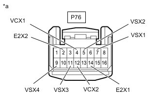
*a Front view of wire harness connector
(to Shift Lever Position Sensor (Transmission Floor Shift Assembly))
Disconnect the shift lever position sensor (transmission floor shift assembly) connector.
-
Measure the resistance according to the value(s) in the table below.
Standard Resistance Tester Connection Condition Specified Condition P76-7 (VSX1) - P76-4 (VCX1) or P76-12 (VCX2) 20°C (68°F) 35 to 43 kΩ P76-5 (VSX2) - P76-4 (VCX1) or P76-12 (VCX2) 20°C (68°F) 35 to 43 kΩ P76-11 (VSX3) - P76-14 (E2X1) or P76-2 (E2X2) 20°C (68°F) 35 to 43 kΩ P76-9 (VSX4) - P76-14 (E2X1) or P76-2 (E2X2) 20°C (68°F) 35 to 43 kΩ -
Reconnect the shift lever position sensor (transmission floor shift assembly) connector.
-
Reconnect the cable to the negative (-) battery terminal.
Result Proceed to OK NG
OK
REPLACE TRANSMISSION FLOOR SHIFT ASSEMBLY Click here
NG
REPLACE SHIFT CONTROL ECU Click here
-