ELECTRONIC SHIFT LEVER SYSTEM, Diagnostic DTC:P176087
| DTC Code | DTC Name |
|---|---|
| P176087 | Lost Communication with Sub Battery Module Missing Message |
DESCRIPTION
The shift control ECU sends backup request signals to the sub-battery ECU (part that is built into the sub-battery module assembly) according to BUBO signals.
The shift control ECU receives backup mode and malfunction notification signals from the sub-battery ECU (part that is built into the sub-battery module assembly) according to BUBI signals.
Communication is performed using PWM communication (Pulse Width Modulation: Modulates pulse width according to duty ratio).
| DTC No. | Detection Item | DTC Detection Condition | Trouble Area | MIL | Warning Indicate |
|---|---|---|---|---|---|
| P176087 | Lost Communication with Sub Battery Module Missing Message | 0.5 seconds or more elapse after turning engine switch on (IG) with battery voltage 10 V or higher, shift control ECU is unable to receive signals from sub-battery ECU continuously for 1 second or more (1 trip detection logic) |
|
Does not come on |
|
CONFIRMATION DRIVING PATTERN
Tech Tips
After repairs have been completed, clear the DTCs and then check that the vehicle has returned to normal by performing the All Readiness check procedure.
-
Turn the engine switch on (IG) and wait for 2 minutes or more.
WIRING DIAGRAM
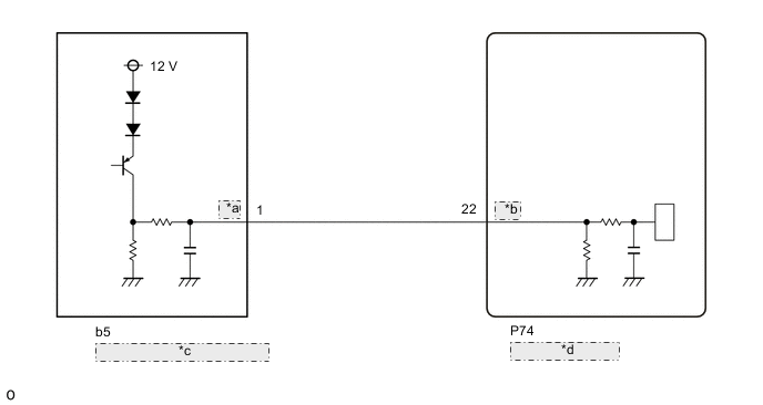
| *a | RO |
| *b | BUBI |
| *c | Sub-battery Module Assembly |
| *d | Shift Control ECU |
CAUTION / NOTICE / HINT
Note
The vehicle is equipped with a sub-battery. Therefore, ensure there is no power being supplied to the vehicle when disconnecting or reconnecting the connector of the shift control ECU and when removing or installing the shift control ECU.
Tech Tips
When a malfunction occurs in the sub-battery control ECU (built into the sub-battery module assembly) power source circuit, communication can no longer be established and P176087 is output.
PROCEDURE
-
CHECK CONNECTOR CONNECTION CONDITION (SHIFT CONTROL ECU CONNECTOR)
-
Check the connector connections and contact pressure of the relevant terminals for the shift control ECU connectors.
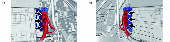
*A for RHD *B for LHD OK The connectors are connected securely and there are no contact pressure problems. Result Proceed to OK NG
NG 
CONNECT SECURELY
OK 
-
-
CHECK HARNESS AND CONNECTOR (SHIFT CONTROL ECU - SUB-BATTERY MODULE ASSEMBLY)
-
Disconnect the P74 shift control ECU connector.
-
Disconnect the b5 sub-battery module assembly connector.
-
Measure the resistance according to the value(s) in the table below.
Standard Resistance (Check for Open) Tester Connection Condition Specified Condition P74-22 (BUBI) - b5-1 (RO) Always Below 1 Ω Standard Resistance (Check for Short) Tester Connection Condition Specified Condition P74-22 (BUBI) or b5-1 (RO) - Body ground and other terminals Always 10 kΩ or higher -
Reconnect the b5 sub-battery module assembly connector.
-
Reconnect the P74 shift control ECU connector.
Result Proceed to OK NG
NG
REPAIR OR REPLACE HARNESS OR CONNECTOR
OK
-
-
CHECK SHIFT CONTROL ECU (CHECK BUBI TERMINAL WAVEFORM)
-
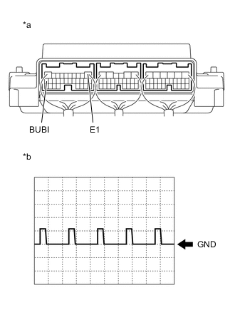
*a Component with harness connected
(Shift Control ECU)
*b Waveform (Sub-battery condition signal) Connect an oscilloscope between the shift control ECU terminals specified in the table below.
-
Turn the engine switch on (IG) and measure the waveform.
Item Contents Terminal BUBI - E1 Equipment Setting 10 V/DIV., 10 ms./DIV. Condition Engine switch on (IG) Tech Tips
The duty ratio changes according to the vehicle condition.
-
Turn the engine switch off.
Result Proceed to OK NG
OK
REPLACE SHIFT CONTROL ECU Click here
NG
-
-
CHECK SUB-BATTERY MODULE ASSEMBLY (CHECK BUBI TERMINAL WAVEFORM)
-
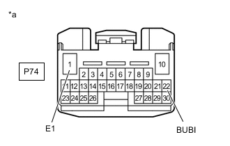
*a Front view of wire harness connector
(to Shift Control ECU)
Disconnect the shift control ECU connector.
-
Connect an oscilloscope between the shift control ECU terminals.
-
Turn the engine switch on (IG) and measure the waveform.
Result Result Proceed to The waveform does not appear A The waveform appears B Note
Turning the engine switch on (IG) with the connector disconnected causes other DTCs to be stored. Clear the DTCs after performing this inspection.
-
Turn the engine switch off.
-
Reconnect the shift control ECU connector.
A
INSPECT SUB-BATTERY MODULE ASSEMBLY Click here
B
REPLACE SHIFT CONTROL ECU Click here
-