ELECTRONIC SHIFT LEVER SYSTEM, Diagnostic DTC:P1761A2
| DTC Code | DTC Name |
|---|---|
| P1761A2 | Gear Shift Control Module "A" System Voltage Low |
DESCRIPTION
Battery power is supplied to the BATT terminal of the shift control ECU. Back-up power is supplied even the engine switch is turned off.
| DTC No. | Detection Item | DTC Detection Condition | Trouble Area | MIL | Warning Indicate |
|---|---|---|---|---|---|
| P1761A2 | Gear Shift Control Module "A" System Voltage Low | With battery voltage 10 V or higher, BATT terminal voltage (ECU recognition value) is below 1 V continuously for 3 seconds or more (1 trip detection logic) |
|
Does not come on |
|
CONFIRMATION DRIVING PATTERN
Tech Tips
After repair has been completed, clear the DTC and then check that the vehicle has returned to normal by performing the All Readiness check procedure.
-
Turn the engine switch on (IG) and wait for 5 seconds or more.
WIRING DIAGRAM
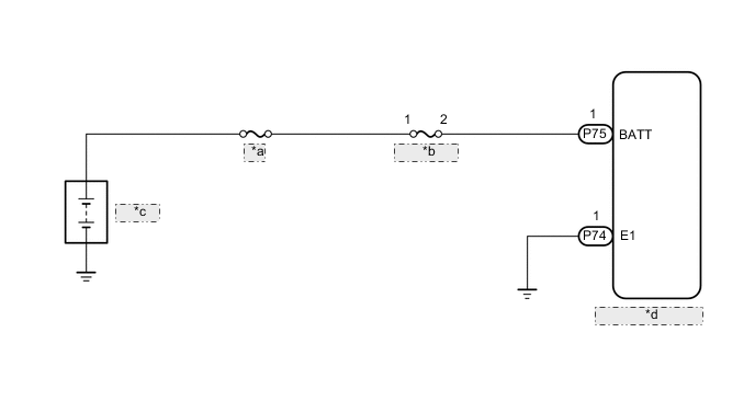
| *a | ENG |
| *b | P CON MAIN |
| *c | Battery |
| *d | Shift Control ECU |
CAUTION / NOTICE / HINT
Note
-
After turning the engine switch off, waiting time may be required before disconnecting the cable from the negative (-) battery terminal. Therefore, make sure to read the disconnecting the cable from the negative (-) battery terminal notices before proceeding with work.
-
The vehicle is equipped with a sub-battery. Therefore, ensure there is no power being supplied to the vehicle when disconnecting or reconnecting the connector of the shift control ECU and when removing or installing the shift control ECU.
-
Inspect the fuses for circuits related to this system before performing the following inspection procedure.
PROCEDURE
-
CHECK CONNECTOR CONNECTION CONDITION (SHIFT CONTROL ECU CONNECTOR)
-
Check the connector connections and contact pressure of the relevant terminals for the shift control ECU connectors.
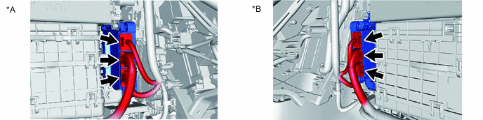
*A for RHD *B for LHD OK The connectors are connected securely and there are no contact pressure problems. Result Proceed to OK NG
NG 
CONNECT SECURELY
OK 
-
-
CHECK BATTERY VOLTAGE
-
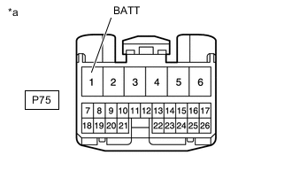
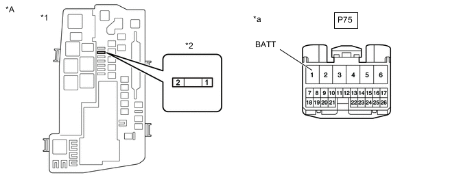
*a Front view of wire harness connector
(to Shift Control ECU)
Disconnect the shift control ECU connector.
-
Measure the voltage according to the value(s) in the table below.
Standard Voltage Tester Connection Switch Condition Specified Condition P75-1 (BATT) - Body ground Engine switch off 8 to 15.4 V -
Reconnect the shift control ECU connector.
Result Proceed to OK NG
OK
REPLACE SHIFT CONTROL ECU Click here
NG
-
-
CHECK HARNESS AND CONNECTOR (SHIFT CONTROL ECU - P CON MAIN FUSE)
-
Disconnect the shift control ECU connector.
-
Remove the P CON MAIN fuse from the No. 1 engine room relay block and junction block assembly.
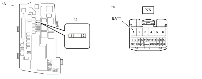
*A for RHD - - *1 No. 1 Engine Room Relay Block and Junction Block Assembly *2 P CON MAIN FUSE *a Front view of wire harness connector
(to Shift Control ECU)
- - 
*A for LHD - - *1 No. 1 Engine Room Relay Block and Junction Block Assembly *2 P CON MAIN FUSE *a Front view of wire harness connector
(to Shift Control ECU)
- - -
Measure the resistance according to the value(s) in the table below.
Standard Resistance (Check for Open) Tester Connection Condition Specified Condition P CON MAIN fuse terminal 2 - P75-1 (BATT) Always Below 1 Ω Standard Resistance (Check for Short) Tester Connection Condition Specified Condition P CON MAIN fuse terminal 2 or P75-1 (BATT) - Body ground Always 10 kΩ or higher -
Reconnect the shift control ECU connector.
-
Install the P CON MAIN fuse.
Result Proceed to OK NG
NG
REPAIR OR REPLACE HARNESS OR CONNECTOR
OK
-
-
CHECK HARNESS AND CONNECTOR (P CON MAIN FUSE - BATTERY)
-
Remove the P CON MAIN fuse from the No. 1 engine room relay block and junction block assembly.
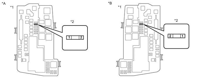
*A for RHD *B for LHD *1 No. 1 Engine Room Relay Block and Junction Block Assembly *2 P CON MAIN Fuse -
Disconnect the cable from the negative (-) battery terminal.
-
Disconnect the cable from the positive (+) battery terminal.
-
Measure the resistance according to the value(s) in the table below.
Standard Resistance (Check for Open) Tester Connection Condition Specified Condition P CON MAIN fuse terminal 1 - Battery positive (+) cable Always Below 1 Ω Standard Resistance (Check for Short) Tester Connection Condition Specified Condition P CON MAIN fuse terminal 1 - Body ground Always 10 kΩ or higher -
Connect the cable to the positive (+) battery terminal.
-
Connect the cable to the negative (-) battery terminal.
-
Install the P CON MAIN fuse.
Result Proceed to OK NG
NG
REPAIR OR REPLACE HARNESS OR CONNECTOR
OK
-
-
CHARGE BATTERY
-
Charge the battery.
Result Proceed to NEXT
NEXT
-
-
CLEAR DTC
-
Connect the GTS to the DLC3.
-
Turn the engine switch on (IG).
-
Enter the following menus: Powertrain / Transmission / Trouble Codes.
Powertrain > Transmission > Trouble Codes -
Check for DTCs and freeze frame data and then write them down.
-
Clear the DTCs.
Powertrain > Transmission > Clear DTCs -
Turn the engine switch off.
-
Disconnect the GTS from the DLC3.
-
Leave the vehicle as is for 60 seconds or more.
Note
-
Do not connect the GTS.
-
Do not depress brake pedal.
-
Do not open/close any of the doors.
Result Proceed to NEXT -
NEXT
-
-
CHECK DTC OUTPUT (SIMULATION TEST)
-
Connect the GTS to the DLC3.
-
Turn the engine switch on (IG) and wait for 5 seconds or more.
-
Enter the following menus: Powertrain / Transmission / Trouble Codes.
Powertrain > Transmission > Trouble Codes -
Check if DTCs are output.
Result Result Proceed to DTC P1761A2 is not output. A DTC P1761A2 is output. B -
Turn the engine switch off.
A
END
B
REPLACE BATTERY Click here
-