ELECTRONIC SHIFT LEVER SYSTEM, Diagnostic DTC:P1765A2
| DTC Code | DTC Name |
|---|---|
| P1765A2 | Sub Battery Module System Voltage Low |
DESCRIPTION
When the engine is started or 5 seconds after turning the engine switch on (IG), the sub-battery power source is supplied to the BUB terminal of the shift control ECU.
| DTC No. | Detection Item | DTC Detection Condition | Trouble Area | MIL | Warning Indicate |
|---|---|---|---|---|---|
| P1765A2 | Sub Battery Module System Voltage Low | Engine running and battery voltage is 10 V or higher, BUB terminal voltage (ECU recognition value) is below 1 V continuously for 3 seconds or more (1 trip detection logic) |
|
Does not come on |
|
CONFIRMATION DRIVING PATTERN
Tech Tips
After repair has been completed, clear the DTC and then check that the vehicle has returned to normal by performing the All Readiness check procedure.
-
Start the engine and wait for 5 seconds or more.
WIRING DIAGRAM
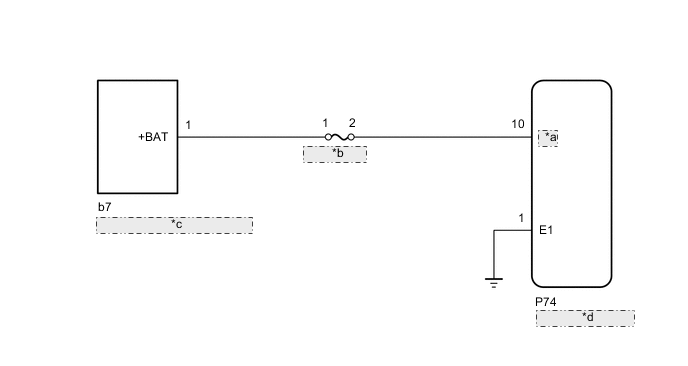
| *a | BUB |
| *b | P CON MAIN2 |
| *c | Sub-battery Module Assembly |
| *d | Shift Control ECU |
CAUTION / NOTICE / HINT
Note
-
The vehicle is equipped with a sub-battery. Therefore, ensure there is no power being supplied to the vehicle when disconnecting or reconnecting the connector of the shift control ECU and when removing or installing the shift control ECU.
-
Inspect the fuses for circuits related to this system before performing the following inspection procedure.
PROCEDURE
-
CHECK CONNECTOR CONNECTION CONDITION (SHIFT CONTROL ECU CONNECTOR)
-
Check the connector connections and contact pressure of the relevant terminals for the shift control ECU connectors.
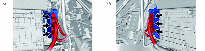
*A for RHD *B for LHD OK The connectors are connected securely and there are no contact pressure problems. Result Proceed to OK NG
NG 
CONNECT SECURELY
OK 
-
-
CHECK SUB-BATTERY MODULE ASSEMBLY VOLTAGE
-
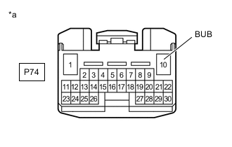
*a Front view of wire harness connector
(to Shift Control ECU)
Disconnect the shift control ECU connector.
-
Turn the engine switch on (IG)
-
Measure the voltage according to the value(s) in the table below.
Standard Voltage Tester Connection Condition Specified Condition P74-10 (BUB) - Body ground 5 seconds after turning the engine switch on (IG) 8 to 15.4 V Note
-
Power is supplied from the sub-battery module assembly for only 5 seconds after the engine switch is turned on (IG). Therefore, measure the voltage during that time.
-
Turning the engine switch on (IG) with the connector disconnected causes other DTCs to be stored. Clear the DTCs after performing this inspection.
-
-
Turn the engine switch off
-
Reconnect the shift control ECU connector.
Result Proceed to OK NG
OK
REPLACE SHIFT CONTROL ECU Click here
NG
-
-
CHECK HARNESS AND CONNECTOR (SHIFT CONTROL ECU - P CON MAIN2 FUSE)
-
Disconnect the shift control ECU connector.
-
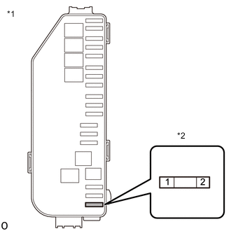
Remove the P CON MAIN2 fuse from the No. 1 luggage room relay block assembly.
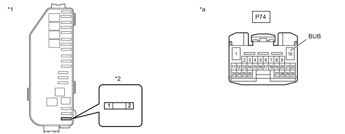
*1 No. 1 Luggage Room Relay Block Assembly *2 P CON MAIN2 FUSE *a Front view of wire harness connector
(to Shift Control ECU)
- - -
Measure the resistance according to the value(s) in the table below.
Standard Resistance (Check for Open) Tester Connection Condition Specified Condition P CON MAIN2 fuse terminal 2 - P74-10 (BUB) Always Below 1 Ω Standard Resistance (Check for Short) Tester Connection Condition Specified Condition P CON MAIN2 fuse terminal 2 or P74-10 (BUB) - Body ground Always 10 kΩ or higher -
Reconnect the shift control ECU connector.
-
Install the P CON MAIN2 fuse.
Result Proceed to OK NG
NG
REPAIR OR REPLACE HARNESS OR CONNECTOR
OK
-
-
CHECK HARNESS AND CONNECTOR (P CON MAIN2 FUSE - SUB-BATTERY MODULE ASSEMBLY)
-
*1 No. 1 Luggage Room Relay Block Assembly *2 P CON MAIN2 Fuse Remove the P CON MAIN2 fuse from the No. 1 Luggage Room Relay Block Assembly.
-
Disconnect the b7 positive (+) terminal from the sub-battery module assembly.
-
Measure the resistance according to the value(s) in the table below.
Standard Resistance (Check for Open) Tester Connection Condition Specified Condition P CON MAIN2 fuse terminal 1 - b7-1(+BAT) Always Below 1 Ω Standard Resistance (Check for Short) Tester Connection Condition Specified Condition P CON MAIN2 fuse terminal 1 or b7-1(+BAT) - Body ground Always 10 kΩ or higher -
Reconnect the b7 positive (+) terminal to the sub-battery module assembly.
-
Install the P CON MAIN2 fuse.
Result Proceed to OK NG
OK
CHECK SUB BATTERY SYSTEM Click here
NG
REPAIR OR REPLACE HARNESS OR CONNECTOR
-