ELECTRONIC SHIFT LEVER SYSTEM, Diagnostic DTC:P272C73
| DTC Code | DTC Name |
|---|---|
| P272C73 | Park Pawl Motor Relay System Actuator Stuck Closed |
DESCRIPTION
The P CON MTR relay and P CON MTR2 relay are activated by signals output from the shift control ECU and supplies power to the shift control actuator assembly (parking lock motor).
When the shift control ECU detects a malfunction of the P CON MTR relay and P CON MTR2 relay, the DTC is stored in the ECM.
| DTC No. | Detection Item | DTC Detection Condition | Trouble Area | MIL | Warning Indicate |
|---|---|---|---|---|---|
| P272C73 | Park Pawl Motor Relay System Actuator Stuck Closed | When the P CON MTR relay and P CON MTR2 relay are both off, voltage at terminal MUA, MVA or MWA of the shift control ECU is 3 V or higher for 0.064 seconds or more. (1 trip detection logic) |
|
Does not come on |
|
CONFIRMATION DRIVING PATTERN
Tech Tips
After repairs have been completed, clear the DTCs and then check that the vehicle has returned to normal by performing the All Readiness check procedure.
-
Turn the engine switch on (IG) and wait for 10 seconds or more.*
Tech Tips
*After performing repairs and clearing the DTCs, the P272C73 fail-safe (3-phase motor power source relay OFF) is continued for 1 trip. As a result, P1C8949 may be output. In this case, "Shift system malfunction Apply parking brake securely when parking See owner's manual" is displayed on the multi-information display. Therefore, perform the following procedures and clear P1C8949 after restoring normal control.
-
Operate the parking brake, turn the engine switch off and wait for at least 2 minutes (If the ODO meter is still illuminated after 2 minutes, wait until it turns off).
-
Start the engine.
Tech Tips
If the DTC was cleared during the previous trip, after starting the engine, the fail-safe is cleared once normal judgment has been completed.
-
Depress the brake pedal and move the shift lever to select drive (D).
-
Drive the vehicle at 40 km/h (25 mph) or more for 10 seconds or more.
CAUTION:
Perform this drive pattern on a level surface and strictly observe the posted speed limits and traffic laws while driving.
-
Stop the vehicle and push the P position switch (shift position indicator) to select park (P).
-
Check that the DTC P272C73 judgment result shows NORMAL by performing the All Readiness check procedure.
-
Clear the DTCs.
Tech Tips
If P1C8949 is output at this time, it may be due to the fail-safe.
-
Turn the engine switch off and wait for 2 minutes or more (If the ODO meter is still illuminated after 2 minutes, wait until it turns off).
-
Turn the engine switch on (IG) and wait for 10 seconds or more.
-
Check that there is no DTCs output.
CAUTION / NOTICE / HINT
Note
-
After turning the engine switch off, waiting time may be required before disconnecting the cable from the negative (-) battery terminal. Therefore, make sure to read the disconnecting the cable from the negative (-) battery terminal notices before proceeding with work.
-
The vehicle is equipped with a sub-battery. Therefore, ensure there is no power being supplied to the vehicle when disconnecting or reconnecting the connector of the shift control ECU and when removing or installing the shift control ECU.
PROCEDURE
-
CHECK RELAY VOLTAGE (P CON MTR RELAY)
-
Remove the P CON MTR relay from the No. 1 engine room relay block and junction block assembly.
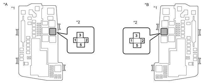
*A for RHD *B for LHD *1 No. 1 Engine Room Relay Block and Junction Block Assembly *2 P CON MTR Relay -
Measure the voltage according to the value(s) in the table below.
Standard Voltage Tester Connection Switch Condition Specified Condition P CON MTR relay terminal 5 - Body ground Engine switch off Below 1 V -
Install the P CON MTR relay.
Result Proceed to OK NG
NG 
CHECK SHIFT CONTROL ECU Click here
OK 
-
-
CHECK RELAY VOLTAGE (P CON MTR2 RELAY)
-
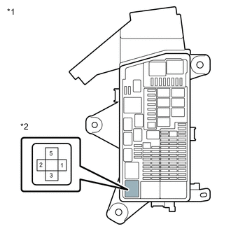
*1 No. 2 Luggage Room Relay Block Assembly *2 P CON MTR2 Relay Remove the P CON MTR2 relay from the No. 2 luggage room relay block assembly.
-
Measure the voltage according to the value(s) in the table below.
Standard Voltage Tester Connection Switch Condition Specified Condition P CON MTR2 relay terminal 5 - Body ground Engine switch off Below 1 V -
Install the P CON MTR2 relay.
Result Proceed to OK NG
NG
CHECK SHIFT CONTROL ECU Click here
OK
-
-
INSPECT P CON MTR RELAY
-
Remove the P CON MTR relay from the No. 1 engine room relay block and junction block assembly.
*A for RHD *B for LHD *1 No. 1 Engine Room Relay Block and Junction Block Assembly *2 P CON MTR Relay -
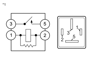
*1 P CON MTR Relay Measure the resistance according to the value(s) in the table below.
Standard Resistance Tester Connection Condition Specified Condition 3 - 5 Battery voltage not applied between terminals 1 and 2 10 kΩ or higher Battery voltage applied between terminals 1 and 2 Below 1 Ω -
Install the P CON MTR relay.
Result Proceed to OK NG
NG
REPLACE P CON MTR RELAY Click here
OK
-
-
INSPECT P CON MTR2 RELAY
-
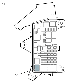
*1 No. 2 Luggage Room Relay Block Assembly *2 P CON MTR2 Relay Remove the P CON MTR2 relay from the No. 2 luggage room relay block assembly.
-
*1 P CON MTR2 Relay Measure the resistance according to the value(s) in the table below.
Standard Resistance Tester Connection Condition Specified Condition 3 - 5 Battery voltage not applied between terminals 1 and 2 10 kΩ or higher Battery voltage applied between terminals 1 and 2 Below 1 Ω -
Install the P CON MTR2 relay.
Result Proceed to OK NG
NG
REPLACE P CON MTR2 RELAY Click here
OK
-
-
CHECK HARNESS AND CONNECTOR (SHIFT CONTROL ECU - P CON MTR RELAY)
-
Disconnect the A53 shift control ECU connector.
-
Remove the P CON MTR relay from the No. 1 engine room relay block and junction block assembly.
-
Measure the resistance according to the value(s) in the table below.
Standard Resistance (Check for Short) Tester Connection Condition Specified Condition A53-12(BMA1) or P CON MTR relay terminal 1 - Body ground and other terminals Always 10 kΩ or higher -
Install the P CON MTR relay.
-
Reconnect the A53 shift control ECU connector.
Result Proceed to OK NG
NG
REPAIR OR REPLACE HARNESS OR CONNECTOR Click here
OK
-
-
CHECK HARNESS AND CONNECTOR (SHIFT CONTROL ECU - P CON MTR2 RELAY)
-
Disconnect the P74 shift control ECU connector.
-
Remove the P CON MTR2 relay from the No. 2 luggage room relay block assembly.
-
Measure the resistance according to the value(s) in the table below.
Standard Resistance (Check for Short) Tester Connection Condition Specified Condition P74-24(BMA2) or P CON MTR2 relay terminal 1 - Body ground and other terminals Always 10 kΩ or higher -
Install the P CON MTR2 relay.
-
Reconnect the P74 shift control ECU connector.
Result Proceed to OK NG
NG
REPAIR OR REPLACE HARNESS OR CONNECTOR Click here
OK
-
-
REPLACE SHIFT CONTROL ECU
Result Proceed to NEXT
NEXT
-
CHECK DTC OUTPUT
-
After repairs have been completed, perform the DTC confirmation driving pattern to run the DTC judgment and check that the DTC judgment result shows NORMAL by performing the All Readiness check procedure (Refer to the CONFIRMATION DRIVING PATTERN for DTC P272C73.).
Tech Tips
After performing repairs and clearing the DTCs, the P272C73 fail-safe (3-phase motor power source relay OFF) is continued for 1 trip. As a result, P1C8949 may be output. In this case, "Shift system malfunction Apply parking brake securely when parking See owner's manual" is displayed on the multi-information display. Therefore, turn the engine switch off and wait for 2 minutes, then turn the engine switch on (IG) and clear P1C8949 after restoring normal control.
Result Proceed to NEXT
NEXT 
END
-
-
REPAIR OR REPLACE HARNESS OR CONNECTOR
Result Proceed to NEXT
NEXT
GO TO STEP 8 Click here
-
REPAIR OR REPLACE HARNESS OR CONNECTOR
Result Proceed to NEXT
NEXT
GO TO STEP 8 Click here
-
REPLACE P CON MTR2 RELAY
Result Proceed to NEXT
NEXT
GO TO STEP 8 Click here
-
REPLACE P CON MTR RELAY
Result Proceed to NEXT
NEXT
GO TO STEP 8 Click here
-
CHECK SHIFT CONTROL ECU
-
*1 No. 2 Luggage Room Relay Block Assembly *2 P CON MTR2 Relay Remove the P CON MTR2 relay from the No. 2 luggage room relay block assembly.
-
Disconnect the A53 shift control ECU connector.
-
Measure the voltage according to the value(s) in the table below.
Standard Voltage Tester Connection Switch Condition Specified Condition P CON MTR2 relay terminal 5 - Body ground Engine switch off Below 1 V -
Reconnect the A53 shift control ECU connector.
-
Install the P CON MTR2 relay.
Result Proceed to OK NG
NG
CHECK HARNESS AND CONNECTOR (SHIFT CONTROL ECU - PARKING LOCK MOTOR (SHIFT CONTROL ACTUATOR ASSEMBLY)) Click here
OK
-
-
REPLACE SHIFT CONTROL ECU
Result Proceed to NEXT
NEXT
GO TO STEP 8 Click here
-
CHECK HARNESS AND CONNECTOR (SHIFT CONTROL ECU - PARKING LOCK MOTOR (SHIFT CONTROL ACTUATOR ASSEMBLY))
-
Disconnect the A53 shift control ECU connector.
-
Disconnect the G41 parking lock motor (shift control actuator assembly) connector.
-
Measure the resistance according to the value(s) in the table below.
Standard Resistance (Check for Short) Tester Connection Condition Specified Condition A53-5(MUA) or G41-2(MUA) - Other terminals Always 10 kΩ or higher A53-2(MVA) or G41-6(MVA) - Other terminals Always 10 kΩ or higher A53-1(MWA) or G41-1(MWA) - Other terminals Always 10 kΩ or higher -
Reconnect the G41 parking lock motor (shift control actuator assembly) connector.
-
Reconnect the A53 shift control ECU connector.
Result Proceed to OK NG
NG
REPAIR OR REPLACE HARNESS OR CONNECTOR Click here
OK
-
-
CHECK HARNESS AND CONNECTOR (PARKING LOCK MOTOR (SHIFT CONTROL ACTUATOR ASSEMBLY) - P CON MTR RELAY, P CON MTR2 RELAY)
-
Disconnect the G41 parking lock motor (shift control actuator assembly) connector.
-
Remove the P CON MTR relay from the No. 1 engine room relay block and junction block assembly.
-
Remove the P CON MTR2 relay from the No. 2 luggage room relay block assembly.
-
Measure the resistance according to the value(s) in the table below.
Standard Resistance (Check for Short) Tester Connection Condition Specified Condition P CON MTR relay terminal 5 or G41-7(BMA) - Other terminals (except P CON MTR2 relay terminal 5) Always 10 kΩ or higher P CON MTR2 relay terminal 5 or G41-7(BMA) - Other terminals (except P CON MTR relay terminal 5) Always 10 kΩ or higher -
Install the P CON MTR relay.
-
Install the P CON MTR2 relay.
-
Reconnect the G41 parking lock motor (shift control actuator assembly) connector.
Result Proceed to OK NG
NG
REPAIR OR REPLACE HARNESS OR CONNECTOR Click here
OK
-
-
REPLACE SHIFT CONTROL ACTUATOR ASSEMBLY
Result Proceed to NEXT
NEXT
GO TO STEP 8 Click here
-
REPAIR OR REPLACE HARNESS OR CONNECTOR
Result Proceed to NEXT
NEXT
GO TO STEP 8 Click here
-
REPAIR OR REPLACE HARNESS OR CONNECTOR
Result Proceed to NEXT
NEXT
GO TO STEP 8 Click here
-
CHECK SHIFT CONTROL ECU
-
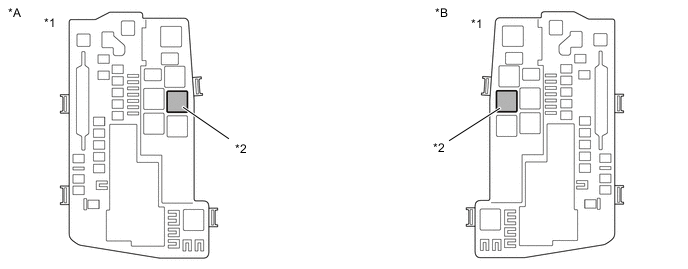
Remove the P CON MTR relay from the No. 1 engine room relay block and junction block assembly.
*A for RHD *B for LHD *1 No. 1 Engine Room Relay Block and Junction Block Assembly *2 P CON MTR Relay -
Disconnect the A53 and P74 shift control ECU connectors.
-
Measure the voltage according to the value(s) in the table below.
Standard Voltage Tester Connection Switch Condition Specified Condition P CON MTR relay terminal 5 - Body ground Engine switch off Below 1 V -
Reconnect the A53 and P74 shift control ECU connectors.
-
Install the P CON MTR relay.
Result Proceed to OK NG
NG
CHECK HARNESS AND CONNECTOR (SHIFT CONTROL ECU - PARKING LOCK MOTOR (SHIFT CONTROL ACTUATOR ASSEMBLY)) Click here
OK
-
-
REPLACE SHIFT CONTROL ECU
Result Proceed to NEXT
NEXT
GO TO STEP 8 Click here
-
CHECK HARNESS AND CONNECTOR (SHIFT CONTROL ECU - PARKING LOCK MOTOR (SHIFT CONTROL ACTUATOR ASSEMBLY))
-
Disconnect the A53 shift control ECU connector.
-
Disconnect the G41 parking lock motor (shift control actuator assembly) connector.
-
Measure the resistance according to the value(s) in the table below.
Standard Resistance (Check for Short) Tester Connection Condition Specified Condition A53-5(MUA) or G41-2(MUA) - Other terminals Always 10 kΩ or higher A53-2(MVA) or G41-6(MVA) - Other terminals Always 10 kΩ or higher A53-1(MWA) or G41-1(MWA) - Other terminals Always 10 kΩ or higher -
Reconnect the G41 parking lock motor (shift control actuator assembly) connector.
-
Reconnect the A53 shift control ECU connector.
Result Proceed to OK NG
NG
REPAIR OR REPLACE HARNESS OR CONNECTOR Click here
OK
-
-
CHECK HARNESS AND CONNECTOR (PARKING LOCK MOTOR (SHIFT CONTROL ACTUATOR ASSEMBLY) - P CON MTR RELAY, P CON MTR2 RELAY)
-
Disconnect the G41 parking lock motor (shift control actuator assembly) connector.
-
Remove the P CON MTR relay from the No. 1 engine room relay block and junction block assembly.
-
Remove the P CON MTR2 relay from the No. 2 luggage room relay block assembly.
-
Measure the resistance according to the value(s) in the table below.
Standard Resistance (Check for Short) Tester Connection Condition Specified Condition P CON MTR relay terminal 5 or G41-7(BMA) - Other terminals (except P CON MTR2 relay terminal 5) Always 10 kΩ or higher P CON MTR2 relay terminal 5 or G41-7(BMA) - Other terminals (except P CON MTR relay terminal 5) Always 10 kΩ or higher -
Install the P CON MTR relay.
-
Install the P CON MTR2 relay.
-
Reconnect the G41 parking lock motor (shift control actuator assembly) connector.
Result Proceed to OK NG
NG
REPAIR OR REPLACE HARNESS OR CONNECTOR Click here
OK
-
-
REPLACE SHIFT CONTROL ACTUATOR ASSEMBLY
Result Proceed to NEXT
NEXT
GO TO STEP 8 Click here
-
REPAIR OR REPLACE HARNESS OR CONNECTOR
Result Proceed to NEXT
NEXT
GO TO STEP 8 Click here
-
REPAIR OR REPLACE HARNESS OR CONNECTOR
Result Proceed to NEXT
NEXT
GO TO STEP 8 Click here