ELECTRONIC SHIFT LEVER SYSTEM, Diagnostic DTC:P1C8F14, P1C9414, P1C9914
| DTC Code | DTC Name |
|---|---|
| P1C8F14 | Park Pawl Motor Phase U Circuit Short to Ground or Open |
| P1C9414 | Park Pawl Motor Phase V Circuit Short to Ground or Open |
| P1C9914 | Park Pawl Motor Phase W Circuit Short to Ground or Open |
DESCRIPTION
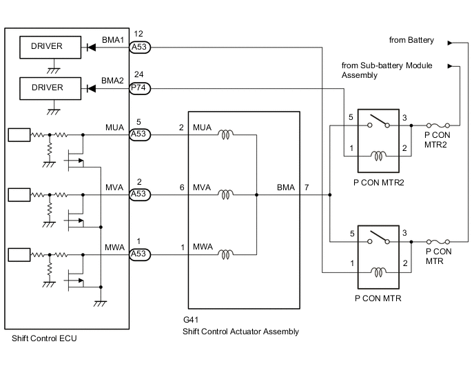
The shift control actuator assembly consists of a parking lock motor, range sensor and rotation angle sensor. The shift control ECU receives shift lever position signals from the shift lever position sensor (transmission floor shift assembly) and P position switch signal from the P position switch (shift position indicator) to operate the parking lock motor through current control to engage and release the parking lock. When the shift control ECU detects a malfunction in the parking lock motor system, the DTC is stored in the ECM.
| DTC No. | Detection Item | DTC Detection Condition | Trouble Area | MIL | Warning Indicate |
|---|---|---|---|---|---|
| P1C8F14 | Park Pawl Motor Phase U Circuit Short to Ground or Open | Even though the P CON MTR relay or P CON MTR2 relay operation permission signal is ON, the parking lock motor U phase terminal voltage (ECU recognition AD value) is continuously below 0.2 V for 1 second or more when the battery voltage and the sub-battery voltage are 10 V or higher with the engine switch on (IG). (1 trip detection logic) |
|
Does not come on |
|
| P1C9414 | Park Pawl Motor Phase V Circuit Short to Ground or Open | Even though the P CON MTR relay or P CON MTR2 relay operation permission signal is ON, the parking lock motor V phase terminal voltage (ECU recognition AD value) is continuously below 0.2 V for 1 second or more when the battery voltage and the sub-battery voltage are 10 V or higher with the engine switch on (IG). (1 trip detection logic) |
|
Does not come on |
|
| P1C9914 | Park Pawl Motor Phase W Circuit Short to Ground or Open | Even though the P CON MTR relay or P CON MTR2 relay operation permission signal is ON, the parking lock motor W phase terminal voltage (ECU recognition AD value) is continuously below 0.2 V for 1 second or more when the battery voltage and the sub-battery voltage are 10 V or higher with the engine switch on (IG). (1 trip detection logic) |
|
Does not come on |
|
CONFIRMATION DRIVING PATTERN
Tech Tips
After repair has been completed, clear the DTC and then check that the vehicle has returned to normal by performing the All Readiness check procedure.
-
Turn the engine switch on (IG)
-
Depress the brake pedal and move the shift lever to select neutral (N).
-
Push the P position switch (shift position indicator) to select park (P).
WIRING DIAGRAM
CAUTION / NOTICE / HINT
Note
-
After turning the engine switch off, waiting time may be required before disconnecting the cable from the negative (-) battery terminal. Therefore, make sure to read the disconnecting the cable from the negative (-) battery terminal notices before proceeding with work.
-
The vehicle is equipped with a sub-battery. Therefore, ensure there is no power being supplied to the vehicle when disconnecting or reconnecting the connector of the shift control ECU and when removing or installing the shift control ECU.
-
The fail-safe function turns the shift control actuator power source relay off when P1C8F14, P1C9414 or P1C9914 is output.
-
Inspect the fuses for circuits related to this system before performing the following inspection procedure.
PROCEDURE
-
CHECK DTC OUTPUT (TRANSMISSION)
-
Connect the GTS to the DLC3.
-
Turn the engine switch on (IG).
-
Enter the following menus: Powertrain / Transmission / Trouble Codes.
Powertrain > Transmission > Trouble Codes -
Check if DTCs are output.
Result Result Proceed to DTC P1C8F14, P1C9414 and P1C9914 are output simultaneously. A Only DTC P1C8F14, P1C9414 or P1C9914 is output. B Tech Tips
-
If DTCs P1C8F14, P1C9414 and P1C9914 are stored at the same time, there may be a malfunction in the parking lock motor (BMA signal) power source circuit.
-
If only DTC P1C8F14, P1C9414 or P1C9914 is stored, there may be a malfunction in the parking lock motor (MUA, MVA or MWA signal) circuit
-
-
Turn the engine switch off.
B 
GO TO STEP 8 Click here
A 
-
-
CHECK HARNESS AND CONNECTOR (P CON MTR RELAY POWER SOURCE CIRCUIT)
-
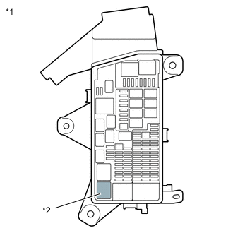
Remove the P CON MTR relay from the No. 1 engine room relay block and junction block assembly.
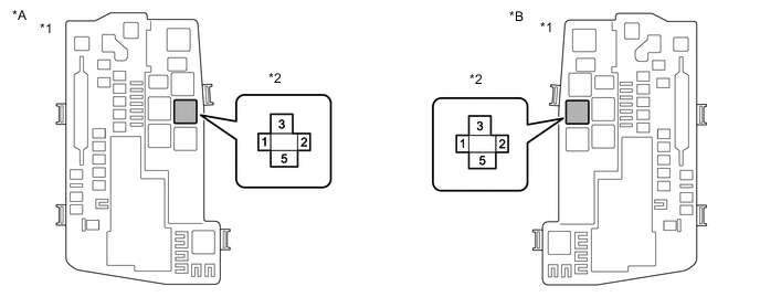
*A for RHD *B for LHD *1 No. 1 Engine Room Relay Block and Junction Block Assembly *2 P CON MTR Relay -
Measure the voltage according to the value(s) in the table below.
Standard Voltage Tester Connection Switch Condition Specified Condition P CON MTR relay terminal 3 or 2 - Body ground Engine switch off 8 to 15.4 V -
Install the P CON MTR relay.
Result Proceed to OK NG
NG
CHECK HARNESS AND CONNECTOR (BATTERY - P CON MTR RELAY) Click here
OK
-
-
CHECK HARNESS AND CONNECTOR (P CON MTR2 RELAY POWER SOURCE CIRCUIT)
-
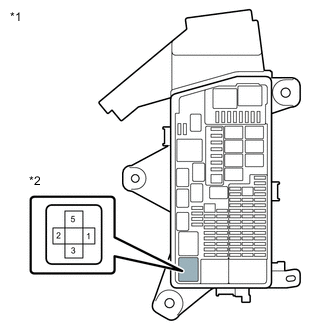
*1 No. 2 Luggage Room Relay Block Assembly *2 P CON MTR2 Relay Remove the P CON MTR2 relay from the No. 2 luggage room relay block assembly.
-
Turn the engine switch on (IG).
-
Measure the voltage according to the value(s) in the table below.
Standard Voltage Tester Connection Condition Specified Condition P CON MTR2 relay terminal 3 or 2 - Body ground 5 seconds after turning the engine switch on (IG) 8 to 15.4 V Note
Power is supplied from the sub-battery module assembly for only 5 seconds after the engine switch is turned on (IG). Therefore, measure the voltage during that time.
-
Turn the engine switch off.
-
Install the P CON MTR2 relay.
Result Proceed to OK NG
NG
CHECK HARNESS AND CONNECTOR (SUB-BATTERY MODULE ASSEMBLY - P CON MTR2 RELAY) Click here
OK
-
-
INSPECT P CON MTR RELAY
-
Remove the P CON MTR relay from the No. 1 engine room relay block and junction block assembly.
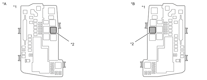
*A for RHD *B for LHD *1 No. 1 Engine Room Relay Block and Junction Block Assembly *2 P CON MTR Relay -
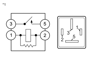
*1 P CON MTR Relay Measure the resistance according to the value(s) in the table below.
Standard Resistance Tester Connection Condition Specified Condition 3 - 5 Battery voltage not applied between terminals 1 and 2 10 kΩ or higher Battery voltage applied between terminals 1 and 2 Below 1 Ω -
Install the P CON MTR relay.
Result Proceed to OK NG
NG 
REPLACE P CON MTR RELAY
OK
-
-
INSPECT P CON MTR2 RELAY
-
*1 No. 2 Luggage Room Relay Block Assembly *2 P CON MTR2 Relay Remove the P CON MTR2 relay from the No. 2 luggage room relay block assembly.
-
*1 P CON MTR2 Relay Measure the resistance according to the value(s) in the table below.
Standard Resistance Tester Connection Condition Specified Condition 3 - 5 Battery voltage not applied between terminals 1 and 2 10 kΩ or higher Battery voltage applied between terminals 1 and 2 Below 1 Ω -
Install the P CON MTR2 relay.
Result Proceed to OK NG
NG
REPLACE P CON MTR2 RELAY
OK
-
-
CHECK HARNESS AND CONNECTOR (PARKING LOCK MOTOR (SHIFT CONTROL ACTUATOR ASSEMBLY) - P CON MTR RELAY, P CON MTR2 RELAY)
-
Remove the P CON MTR relay from the No. 1 engine room relay block and junction block assembly.
-
Remove the P CON MTR2 relay from the No. 2 luggage room relay block assembly.
-
Disconnect the G41 parking lock motor (shift control actuator assembly) connector.
-
Measure the resistance according to the value(s) in the table below.
Standard Resistance (Check for Open) Tester Connection Condition Specified Condition P CON MTR relay terminal 5 - G41-7(BMA) Always Below 1 Ω P CON MTR2 relay terminal 5 - G41-7(BMA) Always Below 1 Ω Standard Resistance (Check for Short) Tester Connection Condition Specified Condition P CON MTR relay terminal 5 or G41-7(BMA) - Body ground and other terminals (except P CON MTR2 relay terminal 5) Always 10 kΩ or higher P CON MTR2 relay terminal 5 or G41-7(BMA) - Body ground and other terminals (except P CON MTR relay terminal 5) Always 10 kΩ or higher -
Reconnect the G41 parking lock motor (shift control actuator assembly) connector.
-
Install the P CON MTR2 relay.
-
Install the P CON MTR relay.
Result Proceed to OK NG
NG
REPAIR OR REPLACE HARNESS OR CONNECTOR
OK
-
-
CHECK HARNESS AND CONNECTOR (SHIFT CONTROL ECU - P CON MTR RELAY, P CON MTR2 RELAY)
-
Disconnect the A53 and P74 shift control ECU connectors.
-
Remove the P CON MTR relay from the No. 1 engine room relay block and junction block assembly.
-
Remove the P CON MTR2 relay from the No. 2 luggage room relay block assembly.
-
Measure the resistance according to the value(s) in the table below.
Standard Resistance (Check for Open) Tester Connection Condition Specified Condition A53-12(BMA1) - P CON MTR relay terminal 1 Always Below 1 Ω P74-24(BMA2) - P CON MTR2 relay terminal 1 Always Below 1 Ω Standard Resistance (Check for Short) Tester Connection Condition Specified Condition A53-12(BMA1) or P CON MTR relay terminal 1 - Body ground and other terminals Always 10 kΩ or higher P74-24(BMA2) or P CON MTR2 relay terminal 1 - Body ground and other terminals Always 10 kΩ or higher -
Install the P CON MTR relay.
-
Install the P CON MTR2 relay.
-
Reconnect the A53 and P74 shift control ECU connectors.
Result Proceed to OK NG
NG
REPAIR OR REPLACE HARNESS OR CONNECTOR
OK
-
-
CHECK HARNESS AND CONNECTOR (SHIFT CONTROL ECU - PARKING LOCK MOTOR (SHIFT CONTROL ACTUATOR ASSEMBLY))
-
Disconnect the A53 shift control ECU connector.
-
Disconnect the G41 parking lock motor (shift control actuator assembly) connector.
-
Measure the resistance according to the value(s) in the table below.
Standard Resistance (Check for Open) Tester Connection Condition Specified Condition A53-5(MUA) - G41-2(MUA) Always Below 1 Ω A53-2(MVA) - G41-6(MVA) Always Below 1 Ω A53-1(MWA) - G41-1(MWA) Always Below 1 Ω Standard Resistance (Check for Short) Tester Connection Condition Specified Condition A53-5(MUA) or G41-2(MUA) - Body ground and other terminals Always 10 kΩ or higher A53-2(MVA) or G41-6(MVA) - Body ground and other terminals Always 10 kΩ or higher A53-1(MWA) or G41-1(MWA) - Body ground and other terminals Always 10 kΩ or higher -
Reconnect the G41 parking lock motor (shift control actuator assembly) connector.
-
Reconnect the A53 shift control ECU connector.
Result Proceed to OK NG
NG
REPAIR OR REPLACE HARNESS OR CONNECTOR
OK
-
-
INSPECT PARKING LOCK MOTOR (SHIFT CONTROL ACTUATOR ASSEMBLY)
-
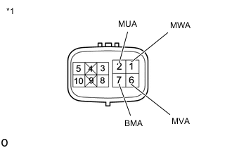
*1 Parking Lock Motor (Shift Control Actuator Assembly) Disconnect the parking lock motor (shift control actuator assembly) connector.
-
Measure the resistance according to the value(s) in the table below.
Standard Resistance (Check for Open) Tester Connection Condition Specified Condition 2(MUA) - 7(BMA) Always 0.5 to 2 Ω 6(MVA) - 7(BMA) Always 0.5 to 2 Ω 1(MWA) - 7(BMA) Always 0.5 to 2 Ω 2(MUA) - 6(MVA) Always 1 to 4 Ω 6(MVA) - 1(MWA) Always 1 to 4 Ω 1(MWA) - 2(MUA) Always 1 to 4 Ω Standard Resistance (Check for Short) Tester Connection Condition Specified Condition 2(MUA) - Body ground Always 10 kΩ or higher 6(MVA) - Body ground Always 10 kΩ or higher 1(MWA) - Body ground Always 10 kΩ or higher -
Reconnect the parking lock motor (shift control actuator assembly) connector.
Result Proceed to OK NG
OK
REPLACE SHIFT CONTROL ECU Click here
NG
REPLACE SHIFT CONTROL ACTUATOR ASSEMBLY Click here
-
-
CHECK HARNESS AND CONNECTOR (SUB-BATTERY MODULE ASSEMBLY - P CON MTR2 RELAY)
-
Disconnect the b7 positive (+) terminal from the sub-battery module assembly.
-
Remove the P CON MTR2 relay from the No. 2 luggage room relay block assembly.
-
Measure the resistance according to the value(s) in the table below.
Standard Resistance (Check for Open) Tester Connection Condition Specified Condition b7-1(+BAT) - P CON MTR2 relay terminal 3 or 2 Always Below 1 Ω Standard Resistance (Check for Short) Tester Connection Condition Specified Condition b7-1(+BAT) or P CON MTR2 relay terminal 3 or 2 - Body ground and other terminals Always 10 kΩ or higher -
Install the P CON MTR2 relay.
-
Reconnect the b7 positive (+) terminal to the sub-battery module assembly.
Result Proceed to OK NG
OK
CHECK SUB BATTERY SYSTEM Click here
NG
REPAIR OR REPLACE HARNESS OR CONNECTOR
-
-
CHECK HARNESS AND CONNECTOR (BATTERY - P CON MTR RELAY)
-
Disconnect the cable from the negative (-) battery terminal.
-
Disconnect the cable from the positive (+) battery terminal.
-
Remove the P CON MTR relay from the No. 1 engine room relay block and junction block assembly.
-
Measure the resistance according to the value(s) in the table below.
Standard Resistance (Check for Open) Tester Connection Condition Specified Condition Battery positive (+) cable - P CON MTR relay terminal 3 or 2 Always Below 1 Ω Standard Resistance (Check for Short) Tester Connection Condition Specified Condition Battery positive (+) cable or P CON MTR relay terminal 3 or 2 - Body ground and other terminals Always 10 kΩ or higher -
Install the P CON MTR relay.
-
Reconnect the cable to the positive (+) battery terminal.
-
Reconnect the cable to the negative (-) battery terminal.
Result Proceed to OK NG
NG
REPAIR OR REPLACE HARNESS OR CONNECTOR
OK
-
-
CHARGE BATTERY
-
Charge the battery.
Result Proceed to NEXT
NEXT
-
-
CLEAR DTC
-
Connect the GTS to the DLC3.
-
Turn the engine switch on (IG).
-
Enter the following menus: Powertrain / Transmission / Trouble Codes.
Powertrain > Transmission > Trouble Codes -
Check for DTCs and freeze frame data and then write them down.
-
Clear the DTCs.
Powertrain > Transmission > Clear DTCs -
Turn the engine switch off.
-
Disconnect the GTS from the DLC3.
-
Leave the vehicle as is for 60 seconds or more.
Note
-
Do not connect the GTS.
-
Do not depress brake pedal.
-
Do not open/close any of the doors.
Result Proceed to NEXT -
NEXT
-
-
CHECK DTC OUTPUT (SIMULATION TEST)
-
Connect the GTS to the DLC3.
-
Turn the engine switch on (IG) and wait for 10 seconds or more.
-
Depress the brake pedal and move the shift lever to select neutral (N).
-
Push the P position switch (shift position indicator) to select park (P).
-
Enter the following menus: Powertrain / Transmission / Trouble Codes.
Powertrain > Transmission > Trouble Codes -
Check if DTCs are output.
Result Result Proceed to DTCs P1C8F14, P1C9414 and P1C9914 are not output. A DTCs P1C8F14, P1C9414 and P1C9914 are output. B -
Turn the engine switch off.
A
END
B
REPLACE BATTERY Click here
-